SATA Protocol Training
SATA Protocol Training. Agenda . SATA Introduction 30 minutes Steve SATA Protocol 100 minutes Eric Layer Architecture Link Layer Physical Layer Phy Layer Frames and the Transport Layer SATA II Bus Doctor SATA Analyzer Demo 30 minutes Eric Q&As 20 minutes. Introduction.

SATA Protocol Training
E N D
Presentation Transcript
Agenda • SATA Introduction 30 minutes Steve • SATA Protocol 100 minutes Eric • Layer Architecture • Link Layer • Physical Layer • Phy Layer • Frames and the Transport Layer • SATA II • Bus Doctor SATA Analyzer Demo 30 minutes Eric • Q&As 20 minutes
Before SAS/SATA • Early 2000 and there are two main non-networked storage drive standards (i.e. Fibre Channel) • ATA/IDE • The most pervasive storage standard in the world (desktop or enterprise) • Renamed to PATA after the introduction of SATA • 18” internal cabling • Host controls a master and slave drive • SCSI • HBA controls up to 15 drives • Used on high-performance workstations, servers, and high-end peripherals; and RAID arrays • U320 is the end of the road for this parallel interface • Host Bus Adapter (HBA) utilizing DMA for maximum I/O • Fibre Channel, ATAPI and SAS have their roots and legacy in SCSI
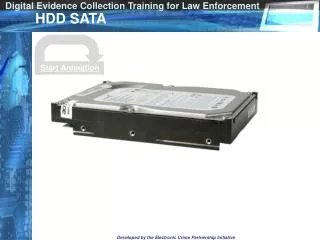
CD SATA HD SATA Where ATA Resides in the PC Architecture
Limitations of Parallel ATA • Bandwidth limited to 133 MB/s • Cyclic Redundancy Checking (CRC) for data but not commands • Support attachment of 2 devices per cable • Small switch or jumper for drive selection • High pin count on signaling interface adds cost to cables, connectors and components • Wide cables are cumbersome and inhibit airflow making cooling more difficult and expensive • Connectors hard to insert and remove • Prone to bent pins
Benefits of Serial Based Storage • Frame-based transaction protocol (OSI model) • Small, inexpensive connectors and cables • Legacy support - ATA stack in SATA • Ease of integration – cabling, jumpers • Point-to-point connections (expanders, port multipliers) • Pathway to higher data rates; 6 Gb/s is on the roadmap • Improve bandwidth • Wide ports permit several simultaneous connections, allowing for link aggregation (SAS) • Lower cost
PATA and SATA Comparisons Source: SATA Working Group
SATA Technology Today • SATA has been the most successful recent new storage interface • It has been a multi billion dollar market for several years • In 2006 over 300 million hard disk drives will have SATA interfaces • 400 Million Shipped in 2005 (source: Gartner) • Market Leader – Seagate 40% share • SATA has also made its appearance in solid state disks, DVD drives and tape drives • In Desktop, notebooks, Consumer Products - DVR • In the Enterprise! (thanks to STP) • Challenges SAS in the enterprise • Non-critical data • Near-line and offline storage • FC, SAS, and SATA will co-exist offering consumers with a choice of flexible storage options at varying price-points
Link Layer – Summary of Functions • Sending/Receiving Frames • 8b/10b encoding • Scrambling/Unscrambling • Flow control • CRC calculation
Link Layer - 8b/10b Encoding • Data transferred across the link must first be converted from 8-bit values (bytes) into 10 bit values (symbols) • Process is called 8b/10b encoding • Invented by IBM • Also used in the following protocols: Ethernet, Fibre Channel • Purpose for encoding • Clock insertion and recovery • Creates sufficient transition density to limit “Run Length” • DC Balance – main “equal” number of 1’s and 0’s • Ability to encode for special control characters (K)
Link Layer - 8b/10b Encoding • Two encodings for each 8-bit value • Dependence on the current running disparity • Two lookup tables are provided for in the specifications
Link Layer – Scrambling/Descrambling • SATA frames are scrambled to help with EMI (primitives are not scrambled) • Scrambling occurs before 8b/10b • “Seeding” resets at the detection of a SOF • Descrambled on receive side after the 8b/10b
ALIGN K28.5 D10.2 D10.2 D27.3 SATA Primitives • Primitives are used as semaphores. They are fixed in content and meaning • Primitive is a dword with one control character followed by 3 data characters • Primitives are used in SATA – the equivalent in Fibre Channel is ordered set • First character is K28.3 (for SATA primitives), or K28.6 (special SATA error primitive) • SATA primitives always send the control character first on the wire first second third fourth
SATA Primitives • The Align primitives establish dword boundaries within the serial bit stream. They are sent as data during OOB, and every 2048 dwords there after Sent First SOF 3 2 1 0 D23.1 D23.1 D21.5 K28.3
SATA Primitives • 18 primitives defined • ALIGN • CONT • DMAT • EOF • HOLD • HOLDA • PMACK • PMNAK • PMREQ_P • PMREQ_S • R_ERR • R_IP • R_OK • R_RDY • SOF • SYNC • WTRM • X_RDY
SATA Primitives • Primitives are used in a variety of circumstances including: • Indicating intent to send an FIS • Indicating beginning and end of each FIS • Flow Control signaling in response to Transport Layer Buffer state • Reporting Transmission Status
Physical Layer - Summary • Defines the connectors and cabling used to transmit and receive SATA signaling and data information
Physical Layer - SATA Device Connector Device connector sizes and locations Appearance of Serial ATA Connectors (Drawing courtesy of Molex) Serial Device plug connector 2.5" power signal Serial ATA signal connector (pin S1) Serial 3.5” Serial ATA power connector (pin P1) Legacy Power (vendor specific) power signal (5.25” form factor also defined for devices like tape drives and DVDs) in comparison… Parallel 3.5” Host receptacle connector 4-pin power parallel ATA signals Graphics courtesy of the SCSI Trade Association and HP
Physical Layer - SATA Cabling SATA to SATA (1), CO, ST The most common internal for SATA (and SAS); 1 meter maximum length SATA Power To provide legacy power support eSATA Power (2m) External SATA; designed for use with external storage products; bypasses the USB route Graphics courtesy of Molex
Physical Layer - Summary • OOB (Out of Band) Signaling • Speed Negotiations • Byte/dword synchronization
Phy Layer - (OOB) • Most primitive level of communication is OOB • They are pattern of idle times and burst times, distinguished by length of time between idles • Idle time (and negation time) are when there are voltage levels • Also known as DC idle • Burst time is during the transmission of the ALIGN primitives • Since byte sync has not occurred yet, the actual bits sent are not relevant – 40 bits will always been detected and consider an ALIGN
Phy Layer - (OOB) • COMINIT/COMRESET and COMWAKE are bursts of 6 ALIGN (0) separated by IDLEs • Length of the idle time determines the type of OOB signal • Senders sends 6 – receiver only need to detect 4 (per spec) • COMRESET are sent by hosts • COMINIT are sent by devices
Phy Layer - OOB COMINIT/COMRESET Electrically, COMINIT and COMRESET appear exactly the same, the only difference is the direction in which the ALIGN patterns are being sent. Host to device: COMRESET; device to host: COMINIT
SATA Power-On Initialization • Starts with the assertion of hardware reset • Begins Out-Of-Band (OOB) signaling • Allows host and device to initialize link communications • Ends with successful transmission of ALIGN primitives • Then speed negotiations
Power-On Initialization Process Host Device
Error Situation Example: Host and Device are unable to establish a connection. Continuous transmission errors are seen from both the Host and Device. No COMINITs present. Indicates problem with Device connection
Primitive Handshaking Sender Receiver X_RDY R_RDY SOF Frame . . . EOF R_IP WTRM R_OK
Primitive Handshaking Example: Host sends commands but commands are not completed Trace indicates that Host is not properly handling primitive handshaking and is not receiving frames
SATA Speed Negotiation • Fast to slow progression • SATA target device sends ALIGN primitives at the fastest supported rate • Waits for host to reply with ALIGNs • If no reply after sending 2048 (i.e., the host doesn’t support this speed), step down to next slower speed and try again
SATA Speed Negotiation • When host replies with ALIGNs, it has locked at the current frequency and negotiation is complete Speed Negotiation
Frames and the Transport Layer • Frames operate at the Transport Layer • Primitives operate at the Link Layer • Frames convey variable content. • A frame starts with a Start of Frame primitive (SOF). • The frame ends with a CRC dword and an End of Frame primitive (EOF). In between the two primitives are dwords that make up the information content
Frames and the Transport Layer • FIS 27 – Used to issue ATA commands to the Device • FIS 46 – Used to transmit Data • FIS 34 – Used by the Device to indicate command completion status • FIS 39 - Used by the device to indicate that it is ready for a DMA transfer • FIS 5F – Used by the device to set up a PIO transfer
Frames Example: Transaction is not completed Trace indicates invalid CRC. R_ERR indicates receiver detected invalid frame.
PATA to SATA • Task File • In the ATA device • In parallel ATA, accesses to these registers result in parallel ATA traffic • In serial ATA, a Shadow Task file register bank is managed by the host (mirrors the ATA device’s task file) • Allows accesses to these registers to be grouped into larger, more efficient serial transfers
PATA to SATA ATA host ATA device PCI bus Parallel ATA Pass-thru Task file IO Reads/Writes SATA host SATA device Serial ATA Shadow task file Task file PCI bus Frame Information Structures
SATA II • Native Command Queuing • Port Selector • Port Multiplier