Download
1 / 22
220 likes | 239 Vues
Design of RFID Tags for the Real World ( and how to test you got it right ) Ian J Forster Clive P Hohberger. AT BEST A well researched detailed description of exactly what is needed, where it will work, on what, when…. AT WORST On napkins…. Tag requirements.

E N D
Design of RFID Tags for the Real World (and how to test you got it right) Ian J Forster Clive P Hohberger
AT BEST A well researched detailed description of exactly what is needed, where it will work, on what, when… AT WORST On napkins… Tag requirements In designing a tag for the ‘real world’ we have to start somewhere with... The REQUIREMENT Summarised as two key parameters: Cost and Performance
Inlay cost and performance drivers • Inlay Performance drivers • Process size used • Parasitic effects • Antenna Conductivity • Assembly technique • Antenna size • Target product range • + Inlay Cost drivers • Area of silicon • Cost of chip • Cost of antenna • Assembly technique • Test methodology • Quality of roll • Wafer yield – chips • Volume • + But… its like pushing on Jell-O, all parameters interact
Lower cost antenna to achieve a given performance Lower threshold sensitivity Smaller Chip Higher assembly cost The blob of Jell-O With cost and performance, everything affects everything else Can I ever say ‘YES’ or ‘NO’… without a ‘BUT’?
OK, now what? • The key is making the right trade-offs in cost and performance to be “good enough” • Robust antenna designs can be made which work well over a wide range of applications • We’ll talk about one such design later.
Transponders are perfect in free space • Nothing is physically there to distort their field or detune their antennas • Reader is so far away that it interacts with the transponder only through the RF signal (“far field”, typically a few wavelengths away– UHF wavelength ~0.34m, so 3 meters is far field) • In the free space and far field, the tag acts like the spec sheet says • Then some idiot goes and slaps it on a carton…
100% RF Transparent ● Bubble wrap ● Dried foods ● Potato chips in foil bags ● Bottled water ● Canned hams ● Jars of pickles 100% RF Absorbing 100%RF Reflecting RF properties of things… • What’s in YOUR carton?
Real products in cartons • Alien squiggle transponder, horizontally polarized • Measured distance at which good read rate drops to 50%
Conductors Dielectrics ‘Mixtures’ = Results in changes in: Antenna bandwidth Operating Frequency Impedance Match Antenna Efficiency… We’re not in free space any more, Toto.. ‘Real World’ influences
And its worse than that… ‘Real World’ Products have a 3D shape Layer of corrugated cardboard Pack of canned goods C T T Antenna position dramatically changes electrical environment tag is operating in C T T
Still worse… Connectivity between conductive objects matter Layer of corrugated cardboard Pack of canned goods C T T So, shape, materials, connectivity all interact with mounting position to determine how well a deployed label works Electrically isolated when pack is bent, in contact at other times And we can’t design a different antenna for each situation…
Special antenna technology approach Avery’s Carton Content Insensitive Technology E field Interaction ‘Near field interaction of specific elements in the antenna design re-tunes the far field response’ When placed 1.7mm away from a set of cans the operating frequency changes by >100MHz H field Interaction Carton Contents Insensitive (CCI) technology is intended to reduce the number of different designs we need to cope with a diverse range of products When placed 1.7mm away from a set of cans the operating frequency changes by <10MHz IN BOTH CHIP CENTRE AND CHIP GAP E field Interaction
Special antenna technology approach • Avery’s CCI Technology allows a single tag design to work on a larger group of products • Works well with metal objects, conductive liquids are a challenge but progress is being made • More difficult to design than a tag specifically tuned for one position and one product • More difficult to test
Avery’s testing systems for real world products • Provides optimal trade-off between • Accuracy • Cost • Speed • Flexibility • Ensures repeatability & traceability to National Standards through • Calibration routines • Test RFID devices • Defined procedures
VECTOR SIGNAL GENERATOR COMPACT ANECHOIC CHAMBER DEVICE UNDER TEST Test Distance LOW DIELECTICSUPPORT REAL TIME SPECTRUM ANALYZER ROTATOR MOTOR IMPORTANT! Does NOT use a reader CONTROL AND DISPLAY SYSTEM Avery primary response testing system Establishes a ‘Baseline’ for all other test systems
Zebra primary response testing system • Built in a G-TEM horn antenna with anechoic foam in bottom • Uniform field in 6x6x6 inch volume • 3-axis motion stepping tests 3-D transponder response field • Uses calibrated UHF reader with PC-controlled step attenuators to measure transponder sensitivity
Avery tag testing on real world products Secondary Reader Based System Calibrated To Primary System
COAXIAL CABLE NEAR FIELD COUPLER READER SYSTEM AND DISPLAY TEST TAG COMPLIANT FOAM POLYSTYRENE BLOCK Avery “sweet spot” tag position testing Tertiary Reader Based System Calibrated To Primary System via secondary system
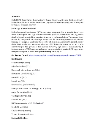
Can I test my own cartons? • Some simple test procedures are in Annex C of:Proposed Guidelines for the Use of RFID-Enabled Labels in Military Logistics: Recommendations for Revision of MIL-STD-129 • Written by the AIM RFID Experts Group • Free from AIM at:https://www.aimglobal.org/estore/ProductDetails.aspx?productID=241
430 mm (17 in) max from natural bottom 25 mm (1 in) min from top Target area for RFID transponder 25 mm (1 in) min from natural bottom 19 mm (0,75 in) minimum from either vertical edge DoD recommended smart label placement • Problem: Where is the best spot to put the label in the allowed target area?
D J D -3 A +2 B +1 C -1 E -1 J -2 H 0dB F -3 G +1 K -1 P 0 Q +1 L +6 M no N +2 Reader threshold power test • Start in the center • Test same tag at different points on case at a fixed distance from a reader with programmable power • Find relative reader power to activate tag at each position • Find position or region requiring minimum power • Put label there!
Questions? Thanks!