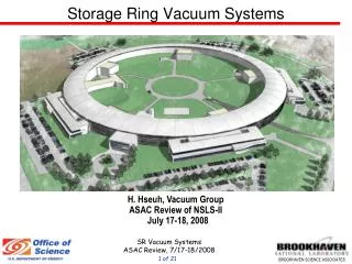
Storage Ring Vacuum Systems
Storage Ring Vacuum Systems. H. Hseuh, Vacuum Group ASAC Review of NSLS-II July 17-18, 2008. Outline. Vacuum System Requirement and Layout Vacuum Chamber Design Prototype Chamber Fabrication Ray Tracing, Absorbers and Pressure Profiles

Storage Ring Vacuum Systems
E N D
Presentation Transcript
Storage Ring Vacuum Systems H. Hseuh, Vacuum Group ASAC Review of NSLS-II July 17-18, 2008
Outline Vacuum System Requirement and Layout Vacuum Chamber Design Prototype Chamber Fabrication Ray Tracing, Absorbers and Pressure Profiles Layout of Straight Sections for ID, Inj. and RF Development in Bellows, BPM Buttons, NEG Strip Support Development in In-situ Bake and Ozone Cleaning Summary
Vacuum Requirements • Vacuum Chambers - Adequate Apertures and Low Impedance • Beam aperture – 25 mm (V) x 76 mm (H) • Chamber straightness - < 1 mm / 5 m • Smooth cross section changes: inclination angle < 10o • Minimum steps or cavities < 1 mm • Mechanical stability: 1 fixed & 2 flexible invar supports at BPMs • P(avg)< 1 nTorr(> 50% H2, < 50% CO, CO2, CH4, …), • Շ (beam-gas) > 40 hr(inelastic scattering) • Local pressure bumps➾bremsstrahlung radiation • Intercept BM photons at discrete absorbers • To protect un-cooled flanges and bellows • Large ion pump and TSP (or NEG cartridge) at absorbers • Two NEG strips in antechamber to provide linear pumping
Cell Vacuum Chamber Layout ID Beamline S2 S3 S1 BM Beamline S4 L.S. Absorbers/pumps S5 S1 S6 S.S. Aluminum Cell Chambers Stainless chambers S2 - 3.6m Dipole chamber, 6o bend S3 - 3m Multipole chamber S4 – 3.3m S5 – 3m S6 – 3.7m
Cell Chamber Cross Sections and Analysis Multipole Chamber Dipole Chamber Extruded Extruded cross section 3 mm wall Bended and machined At Quadrupole Maxi. δ = 0.3 mm x2 Max. S = 42 MPa Machined at pole locations At Sextupole 3.1 mm wall Maxi. δ = 0.27 mm x2 Max. S = 64 MPa Syield (A6063T5) = 145 MPa Sstress (A6063T5) = 186 MPa
Aluminum Cell Chamber Fabrication L. Doom Extrusion➾ bending ➾ machining ➾ cleaning ➾ welding ➾ assembly …. $$$ $ $ $ $$ $$ V #1,2 V #3 V #4, 5, 6… APS APS BNL End plate Machining Extrusions Machining End Assy End plate & bi-metal flanges Test extrusion with two vendors completed Fabricate two S4 chambers by Sept Machining by CS and by vendor started Weld development by APS started Bending of dipole extrusions starts soon Welding at APS
DW absorber DW fan Damping Wiggler Damping Wiggler Multipole Dipole Multipole DW fan: 32 kW x 2, ± 2.6 mrad canted by ± 1.8 mrad EPU fan: 6 kW x 2, ± 0.46/0.77 mrad canted by ± 0.12 mrad? IVU fan: 8 kW, ± 0.31 mrad Dipole fan:2.4 kW, 105 mrad Dipole Flange absorber Stick absorber Multipole Crotch absorber Ray Tracing of Photon Fans • To define photon fans and absorber locations • ➾ To ensure adequate apertures for photon fans • ➾ To protect un-cooled flanges and bellows • ➾ To estimate power, density and ΔT for absorbers, and P profile
DW and BM Photon Fans at S1-S4 Region M. Ferreira S2 S3 S4 DW ABS > 15 kW S2 S3 S3 Larger bellows and RF fingers to accommodate canted DW fan Vertical fan hitting Top/bottom wall S4A S4B SourceLocationP(W) BM S3, S6 ~5EPU S1-S3 < 35 IVU20 S1 160* DW S1 166 S2 280 S3 270 Large SR power intercepted here Limited space for pumping ports and multipoles *on magnet shields
Simulation of DW vertical power using SPECTRA8 M. Ferreira S2 S1A S1B S3 DW 1 DW 2 h = 10 - 25 mm h = 15 - 25 mm h ~ 9 mm From DW1 + 1.8 mrad P = 166 W P = 274 W P = 230 W From DW2 - 1.8 mrad P = 6 W P = 40 W DW fan profile ΔP < 0.5 W/cm2 ΔP < 0.3 W/cm2 Power and density are not excessive for S2 and S3 chambers Flange absorbers may be added at S1A-S1B, S1B-S2, and S2-S3? to trim vertical fan effectively, still with reasonable impedance
Photon Absorbers (8-10 per cell) Flange Crotch Stick Crotch in dipole Stick in multipole Damping Wiggler Absorber < 3 W/mm2, Tmax ~ 68oC < 12 W/mm2, Tmax ~ 200oC BM Absorber Positions and Power Absorber brazing development started
Absorber Positioning vs. Aperture Requirement W. Guo --± 3% aperture Δ ABS +X position
Molflow Code (R. Kersevan/ESRF) Pressure Profile with and without DW E. Hu Local ΔP w/ 15% DW fan ➾ bremsstrahlung radiation To be updated Pavg = 0.25 nT SS LS 3 GeV, 0.5A, η = 1x10⁻⁵ Pavg = 0.13 nT
Layouts for Insertion Device Straights ID Chamber Design: Chamber inner height ≈ magnet gap - 3 mm Extruded Al with NEG strips in antechamber Or extruded Al w/NEG coated h = 7.5 mm, 1.25 mm wall APS ID chamber h = 8 x 57 mm, 1mm wall ESRF NEG coated chamber 9.3 m straight for 2 x 3.5 m DW 6.6 m straight for 2 x 2 m EPU Limited space for stand-alone ID BPMs
Layouts for Injection and RF Straights Bellows + transition Injection Straight RF Straight Working closely with AP, Diag, Magnet and other systems on the layout of special components
Choice of RF Shielded Bellows M. Ferreira RF Bellows Requirements: Max mis-alignment: 2 mm; Max comp/extension: ± 12 mm; Max angle deviation: 15 mrad Inside fingersOutside fingers (APS, LNLS) (Soleil, Diamond, etc) Simple, reliableLower impedance $$ $$$ inside fingers loss = 10 mV/pC outside fingers inconel springs Outside fingers Wider fingers Fewer fingers 3D model for impedance simulation Inside or outside fingers? Be-Cu fingers Solid sleeve
Impedance of Other Vacuum Components Work closely with AP on vacuum components impedance simulation and approval A. Blednykh S4A chamber with absorber and shielded pumping ports S4A absorber and pump port GV RF shields Multipole chamber with stick absorber and pumping ports Dipole chamber with crotch absorber and pumping ports Flange absorber
Mounting of BPM Buttons/Flanges P. Cameron Optimum design: 7 mm Ø buttons, 16 mm apart? (O. Singh’s talk) 50 16 CD-2 Design 10mm Ø button /34 mm Ø flange /Helicoflex seal 25 12 mm wall may be too thin for bolts/inserts & sealing 15 mm wall? 2 Rectangular flange? Sealing reliability? 7mm Ø 12 mm apart w/ 44 mm Ø flange
NEG strip supports L. Doom, K. Wilson Riveted mounting every 10cm, with alumina insulators on carrier plates Prototype to be tested on APS chambers for reliability and flexibility NEG strips in Antechamber NEG support development using APS chambers
In-situ Bake with External Heaters M. Ferreira, F. Lincoln T ~120oC achievable with foil heaters mounted at drift space (< 1 kW/m) Need to optimize power, heater temp, non-magnetic, insulation, etc Eliminate the needs of high P, hot water system, a major ES&H concern APS chambers for bakeout development
Ozone Cleaning Development K. Wilson Flush chamber with < 500 ppm O3in O2 to break and remove contaminants Process developed by T. Momose, KEK Final cleaning prior to installation (after alignment…) Extensive O3 monitoring to meet ES&H requirements System being assembled for testing Ozone system flow diagram
Summary • Cell vacuum chamber design is well advanced • Test extrusion of both cross sections completed with two vendors • Machining and weld development of prototype chambers are underway • Ray tracing and absorber development continues • Straight section layouts for ID, RF and Inj has started • RF shielded bellows design has started • Work with AP on vacuum component impedanace • Work with Diag. on finalizing BPM button/feedthru design. • NEG strip supports developed and is being tested • Chamber bakeout with foil heaters is successful • Ozone cleaning system developed and is ready for evaluation