Download
1 / 13
130 likes | 147 Vues
Explore the representation of data in binary form in computer systems and the basics of logic gates, logic circuits, and truth tables. Understand the importance of binary representation for computer operations.

E N D
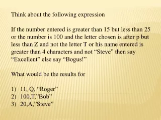
Think about the following expression • If the number entered is greater than 15 but less than 25 or the number is 100 and the letter chosen is after p but less than Z and not the letter T or his name entered is greater than 4 characters and not “Steve” then say “Excellent” else say “Bogus!” • What would be the results for • 11, Q, “Roger” • 100,T,”Bob” • 20,A,”Steve”
Candidates should be able to: • explain why data is represented in computer systems in binary form • understand and produce simple logic diagrams using the operations NOT, AND and OR • produce a truth table from a given logic diagram. GCSE Computing BINARY LOGIC
The denary (decimal) system that we use has 10 digits (0-9). • For a computer systems to use denary it would need to be able to store and transmit 10 different ‘states’. • It is therefore much simpler for computer systems to use the binary number system because it has just 2 digits (0-1) which can easily be represented and stored as 2 different states. • Examples of different ‘states’ used to store/transmit binary data: • ON / OFF (a semi-conductor switch, used in computer memory) • TRANSMIT / DON’T TRANSMIT (an electrical signal, used to transfer binary data) • NORTH / SOUTH (areas with different magnetic polarity, used to store binary data on magnetic media) • REFLECT / NON-REFLECT (reflective and non-reflective areas, used to store binary data on optical media) Why is data represented in computer systems in binary form?
In computer science, the Boolean or logical data type is a data type that has two values (usually denoted true and false). Logic gates are physical devices that can carry out Boolean logic functions. The three basic logic gates are the AND, OR and NOT gates. What are logic gates?
The symbol for an AND gate is shown below. OUTPUT O is only true if INPUT AANDINPUT Bare both TRUE. This can be representedby this truth table. It can also be representedby this logic statement:O = A AND B An AND gate carries outBoolean multiplication (i.e. TRUE * FALSE = TRUE) The AND gate
The symbol for an OR gate is shown below. OUTPUT O is true if INPUT AOR INPUT Bare TRUE. This can be representedby this truth table. It can also be representedby this logic statement:O = A OR B An OR gate carries outBoolean addition (i.e. TRUE + TRUE = TRUE) The OR gate
The symbol for a NOT gate is shown below. OUTPUT O is true if INPUT A is NOT TRUE. This can be representedby this truth table. It can also be representedby this logic statement:O = NOT A A NOT gate carries outBoolean inversion(i.e. TRUE = FALSE) The NOT gate
A logic diagram is a diagram that represents one or more of logic gates linked together to form a logic circuit. • In logic diagrams; • Symbols are used to represent logic gates • Letters are used to label the input(s) and output(s) • Lines are used to show how logic gates are connected. What are logic circuits?
For each logic diagram, complete a truth table and create a logic statement. Example problems
For each logic statement, complete a truth table and create a logic diagram. • O = (NOT A) AND (NOT B) • O = NOT (A OR (NOT B)) Example problems
For each truth table, create a logic diagram and create a logic statement. Example problems


![TATT [Think about the Trees]](https://cdn3.slideserve.com/6506657/tatt-think-about-the-trees-dt.jpg)