Download
1 / 76
760 likes | 928 Vues
NS1000. Demo Set-up and installation. Configuration Diagram. Maintenance Console. Outlook IMAP Integration. NS1000. SLT Connection. PC. PSTN Connection. Router / Switch. LAN. PSTN Network. GSM Network. FAX. NT Series (Optional). UT Series. GSM Integration. System Initialisation.

E N D
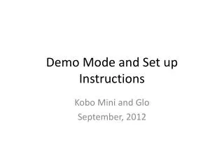
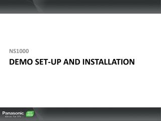
NS1000 Demo Set-up and installation
Configuration Diagram Maintenance Console Outlook IMAP Integration NS1000 SLT Connection PC PSTN Connection Router / Switch LAN PSTN Network GSM Network FAX NT Series (Optional) UT Series GSM Integration
System Initialisation BATT ALARM MASTER STATUS Before making any programming changes, initialize the system (factory default settings) to clear any previous configurations. • Ensure the power switch is OFF (Back of Unit). • Slide the System Mode Switch to the “SYSTEM INITIALIZE” position. • Turn the power switch ON. (STATUS and MASTER LED will flash AMBER), the STATUS LED will then flash GREEN. • While the status LED is flashing, slide the System Mode Switch back to the “NORMAL” position. • When successfully executed, the STATUS indicator will stop flashing and stay lit. (RED or GREEN). System Mode Switch Indicators STATUS = RED (No DHCP) STATUS = GREEN (DHCP) MASTER = Flashing AMBER (Master/Slave not assigned) Note This needs to be done on both Master and Slave units.
Web Console Preparation • Below are the system requirements necessary for Web Connection to the NS1000 • PC Requirements Supported Browsers Browser Settings • Enable the following functions in the browser's settings: • Cookies • JavaScript • The ability to download files • The display of animations • The display of images Windows Internet Explorer 7 or 8 Mozilla Firefox 4 Apple Safari 5
Web Console Connection • When the system has been initialized, the Setup Wizard can be run via the Web Maintenance Console (Web-MC). • Connecting a PC to the NS1000 via the Web-MC • For Demo purpose we will assume that the PC connected for maintenance will also run CA, Outlook, and IMAP. In this instance we will use the LAN port for connection. The Maintenance (MNT) port can be used when connecting a PC just for programming. This is not covered in this presentation. • Set your PC in the same IP range as the NS1000 (NS1000 Default IP address: 192.168.0.101) • Connect your PC to the LAN Port of the NS1000 • Open you Browser and enter the URL http://192.168.0.101 • The Web Maintenance Console login screen will then be displayed in your browser. • User Name Default: INSTALLER, Password Default: 1234 • NOTE • After the system has been initialized the IP Address for both units will be the same. Only connect ONE unit to the network at a time. It is recommended that the SLAVE unit is configured first. This way only one IP address needs to be changed on setup and the Master Unit IP address can remain the same. The Slave unit can then remain on the network when the Master unit is added.
Web Console Overview Upon LOGIN, you are presented with the ‘Home’ Screen Home Screen Icon Loads the Home screen. PBX Slaves Displays the Maintenance screen. Displays the Setup screen. Saves the data. Opens the on-line help. PBX Master Displays the Web MC version info. Saves the data and logs you out. Adds slave units. Displays the Home screenin icon view. Displays the Home screenin list view.
Web Console Overview - 2 Using the ‘List’ view in the ‘Home’ Screen allows you to see the PBX Type (Master/Slave), IP-Address, MAC address, S/W Version and Region type of all PBXs in a One-Look system. List View PBX Status PBX System Information is shown here.
System Firmware Download • Before the system or terminals can be upgraded, new Firmware must first be downloaded to the System. This can be a Manual or Automatic process depending on the system settings; • Manual Download example - Download from PC (USB and FTP also available) Select the Maintenance screen Select the location of the new Firmware file. Click ‘Execute’ Click ‘OK’ and the prompt, and the Download process will start. File Download takes approximately 4~5 min for PCMPR (PBX System) firmware
PBX System Firmware Upgrade - 1 • Once downloaded, the new firmware can be ‘pushed’ to the relevant device Manually or Automatically • System Upgrade (1) - Manual 1. System Control -> Program Update -> Update Program File 2. Select the Update Type (Manual, Timed or Cancel) 3. Select Email notification recipients 4. Select the File to be used for the upgrade 6. Select ‘Apply’, then ‘Execute’ to start the upgrade process 5. Select the upgrade target (Device) 7. Click ‘OK’ to complete
PBX System Firmware Upgrade - 2 • The Plug and Update feature allows IP-PTs to be automatically updated to the latest software version when they are registered to the PBX. • Plug and Update 1. System Control -> Program Update -> Update Program File Select ‘On’ or ‘Off’(Default) When Plug and Update is enabled, the version number of the system software stored on the Master unit is compared to the system software currently in the IP-PT, after the IP-PT has been registered to the PBX. If the software on the Main unit is newer, it is downloaded to the IP-PT. Plug and Update can be enabled for each site in a One-look network. The Plug and Update screen lists the PBXs in the One-look network by site number and site name.
Check Firmware Version • It is possible to check the Firmware versions of each device – this allows you to ensure that a software upgrade was successful. • PBX Firmware version – check: The PBX Version can be viewed by selecting the ‘Home’ screen and ‘List’ View The PBX Firmware Version can be seen here
Setup • Location Setting • 1. Set the unit status as Master, and change the Suffix and Area if necessary. Set the unit as Master Set the unit Suffix Code (UK, NE, CE, GR etc) and your required country. The Suffix Code can be found on the units Nameplate and box Click ‘Next’ to continue. • It is important to select the correct Suffix/Country settings so that the correct default tones, emergency dial and other country specific data are set automatically.
Setup • PBX Setting • 2. Give the system an appropriate name and set the Time Zone Use a name which easily identifies the unit. Select the Time Zone. The Local date and time are obtained automatically from your PC. Check that the PC date/time is correct. Click ‘Next’ to continue.
Setup • LAN Setting • 3. Use the Default LAN settings. By default, the PBX uses a static IP Address (Recommended) Configure DNS if required. By default, the DSP Cards use DHCP to obtain an IP-Address, however static addresses can also be assigned. Click ‘Next’ to continue.
Setup Registration Setting 4. Enter the IP Terminal Registration Mode as Manual. Full automatic can be used but is not covered in this document. Manual entry reduces the number of Empty Extension numbers in CA. Activate the 60-day One-Look Trial. Click ‘Next’ to continue. • Note: • Non-UT Series SIP Terminals must be registered manually. • By default, the UT-Series SIP Extension password is automatically set to ‘1234’
Setup SNTP (Simple Network Time Protocol) / Daylight Saving Setting 5. The source used for automatic time adjustment and the Daylight Saving mode is set here. This is useful to keep the time displayed on the terminals and SMDR records etc accurate. Automatic Time Adjustment can be made using ISDN/Analogue Trunks (ISDN/FSK) or via a suitable SNTP server. For countries using ‘Daylight Saving’ - automatic adjustment can be set here. Click ‘Next’ to continue.
Setup • Maintenance / Remote Management Settings • 6. The Installer Password can be changed if required. Even if you want to keep as default (1234) you must re-enter it here before continuing. Even if you want to keep the default password you must re-enter it before continuing. Click ‘Finish’ to complete.
Adding Extensions • Click on Configuration – Slot – Virtual. Install a V-UTEXT32 card and select the number of cards and the users. Select 1.1 ‘Slot’ -> ‘Virtual’ Install the V-UTEXT32 Card and set the number of cards and users.
Adding Extensions Click ‘OK’ to install the V-Ext card. Select ‘Out Of Service’.
Adding Extensions Select ‘Port Property’. Set the Ext number and Password. Click ‘Apply’, then ‘OK’. Note: By Default, the Password is set to ‘1234’
Adding Extensions Set the port ‘In Service’.
UT Series Registration • To register a UT series terminal, click on the IP-Phone Registration button and select ‘SIP-MLT’. Select ‘IP-Phone’ Registration -> ‘SIP-MLT’ Select ‘Registration’.
UT Series Registration • Select the desired Extension from the list and follow the on screen prompts. • The UT Terminal will then register with the PBX.
UT Series Registration Confirm the registration 11. After the UT-PT has re-booted and the WebMC Registration process has been completed, the UT-PT will be in-service. 10 OCT. 12:09PM MON 103 Setting Call Log Menu Further Extension configuration can now be made via the WebMC, using the Extension Number of the IP-PT. From the V-UTEXT32 Port Properties screen, the UT registration status, Password, MAC, IP-Address and firmware version can be seen.
Create a User Profile • To enable other users to manage their own telephone features, unified messaging and email notifications, users require a suitable User Profile. • Specify the Users name (First Name is required) From the ‘Settings’ Menu, select ‘Users’ -> ‘Add User’ In the ‘User Information’ Tab, a First Name MUST be set.
Create a User Profile • Specify the Users Extension Number In the ‘Contact’ Tab, specify the Users Ext Number.
Create a User Profile • Create a Mailbox for the User In the ‘Unified Message’ Tab, specify the UM group and the desired Mailbox Number. (A Mailbox will be created automatically using this Mailbox Number)
Create a User Profile • Specify the Login ID and Password for the User Profile Set the Login ID and Password for the User Profile. This will allow the Users to Login to their User Profile via the Web MC and make any necessary changes to their User Profile or PT Settings
Introduction • Outline of UM Functions • The Built-in Unified Messaging System (UM) takes over the functions of current TVM voice processing system. • Fax Server, IMAP4 Integration and 2-Way Recording control features are added to build a Unified Messaging system. • Built-in • Voice Mail • Auto Attendant and IVR function/features • Activation Keys • 2 channel / 4 channel • IMAP4 / email / Fax • 2 way recording • 2 way recording control Unified Voice, FAX, Email Email Server (IMAP/POP3) Outlook Fax to email as a .TIFF attachment for incoming faxes*. Print to Fax directly from your PC applications* *Using Optional FAX Interface
Installing the Required A/Ks Install the required Activation Keys • UM Email Client (To allow FAX / Email) , 1 per required user. There are no special Port/Trunk Service setting required for the UM Ports. Only installation of the FAX Server card is required.
Create the required Mailboxes • Via the WebMC, Add the desired number of Mailboxes Settings -> UM Configuration -> 1. Mailbox Settings Add Mailbox
Create the required Mailboxes • Configure the Basic Mailbox Settings • Enter: • The Mailbox Number • The Extension Number (If required) • Mailbox Password • Message Client Password (For Fax Driver) Click ‘OK’
Create the required Mailboxes • Enter both the Mailbox Password and the Message Client Passwords The Mailbox Password is required to allow a user to access their Mailbox. The Message Client Password is required when using the Fax Driver software to send a FAX from your PC. It is recommended to use strong passwords.
UM Floating Extension (Group) Number • The UM System can be accessed via a single ‘Floating’ Extension number (Default:500) • By using this ‘Floating’ number, CO and Ext calls can be easily directed to the UM System. PBX Configuration -> 3. Group -> 7. UM Group -> Unit Settings Master System UM Floating Extension Number is 500 (default) (Each Distributed UM will have their own Floating Ext Number) For Example, If an extension user wants to FWD Calls to their Mailbox, they would C-FWD to ‘500’.
UM Floating Extension (Group) Number • By setting the DDI Destination Table to the UM ‘Floating’ Extension number (Default:500); • CO calls can be directed to the UM System. PBX Configuration -> 10. CO & Incoming Call-> 3. DDI Table DDI Destination can be set for each Time Mode Note: By setting the appropriate DDI Destination, calls can arrive at the UM or DISA Systems, ICD-Gs or extensions, based on the Time Mode setting.
Accessing Messages and Faxes Accessing UM Mailboxes and Managing Fax Messages Messages Received at a ‘Central’ Mailbox can be accessed from an extension in the following way: • Call the UM Floating Extension Number (500) • At the Greeting Message dial ‘#6* + Mailbox Number’ • Enter the Central MBX Password at the prompt Messages Received directly in your Extension Mailbox can be accessed by calling the UM Floating Extension Number(500) and then entering your Password. To Manage Fax Messages: • Access the desired MBX • Select the option to listen to Messages (‘1’ for New, ‘3’ for Old) • Listen to Fax Message Envelope – Press ‘2’ • Follow the prompts as necessary; • Press ‘5’ to transfer the Fax • Press ‘7’ to print the Fax via a connected FAX Machine.
IMAP Overview • The Built-in UM supports the IMAP4 protocol and works as a voice and fax IMAP4 server. • A User can retrieve, delete, transfer, reply, and send messages by using a common email client which supports IMAP4 (like Outlook, Lotus Notes, etc). • UM subscribers just need to add an additional IMAP4 email account to their email client to be able to use the UM features. • No additional client software installation is required. • Activation Key - UM Email Client (To allow FAX / Email) , 1 per required user. NS1000 IMAP 4 Server Email Server IMAP 4 IMAP 4 / POP3 PC with Email Client (e.g. Lotus Notes) Note: Outlook 2010 is not supported at this time.
Installing the Required A/Ks Install the required Activation Keys: • UM Email Client (To allow FAX / Email) , 1 per required user. Note: Max 24 simultaneous IMAP connections to NS1000. If more than 24 IMAP Users then each user should use Outlook in ‘Offline’ mode.
Setting the UM Class Of Service for IMAP • To enable IMAP / OUTLOOK integration with an existing UM Mailbox , ‘Desktop Messaging’ option must be set to ‘YES’ in the UM Class of Service. UM Configuration -> 2. Class Of Service -> General, set DESKTOP MESSAGING to ‘YES’ Click ‘OK’
Creating an IMAP account in Outlook • It is necessary to add an additional Email account to integrate with the NS1000. • From the PC, Open ‘Outlook’ 1. Select ‘Tools’ -> ‘Account Settings’ 2. Open the ‘Email’ Tab and Click ‘New’ Note: Screen Shots may differ depending on the version of Outlook used (2007)
Creating an IMAP account in Outlook • Configure the IMAP Account details 3. Select the IMAP Option and click ‘Next’ • Select the option to Manually configure the Sever Settings and click ‘Next’ 5. Select the Internet Email Option and click ‘Next’
Creating an IMAP account in Outlook • Configure the IMAP Account details (Users Mailbox) 6. Enter the Users Mailbox Number and their email address (Mailbox@PBX_IP_Address) 7. Enter the Account Type (IMAP) and the Server Location (PBX_IP_Address) 8. Enter the User Name (Mailbox) and Message Client Password – Click ‘Next’ 10. Click ‘Finish’ 9. New ‘IMAP’ Account will be created
Creating an IMAP account in Outlook • Accessing Voice / FAX Messages The new IMAP Account is created and Messages can be seen in the viewing pane Voice Messages are in .wav format and can be opened with Windows Media Player. Codec: CCITT A-law, 64kbps, 8kHz, 8bit, Mono Voice Messages are in .tiff format and can be opened in Windows Picture/Fax Viewer. Once the Message has been ‘Read’, the Message Waiting Lamp on the PT will turn off.