Exploring Water Wave Phenomena: Ripple Tank Experiments
Learn about wavefronts, reflection, refraction, diffraction, and interference of water waves in this detailed ripple tank experiment guide.

Exploring Water Wave Phenomena: Ripple Tank Experiments
E N D
Presentation Transcript
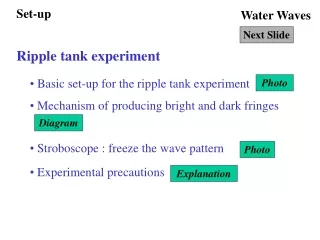
Set-up Water Waves Next Slide Ripple tank experiment • Basic set-up for the ripple tank experiment Photo • Mechanism of producing bright and dark fringes Diagram • Stroboscope : freeze the wave pattern Photo • Experimental precautions Explanation
Wavefronts Water Waves Next Slide Wavefronts and rays • Straight wavefronts and circular wavefronts Diagram • Rays : the direction of travel of the wavefronts Diagram
Wave Phenomena 1 Water Waves Next Slide Reflection of waves • Reflection of water waves by a straight barrier Photo • Reflection of water waves by curved barriers Photo • Effects of reflection on frequency, wavelength and speed Diagram
Wave Phenomena 2 Water Waves Next Slide Refraction of waves • Method of creating different media for water waves Diagram • Refraction of water waves Photo • Effects of reflection on frequency, wavelength and speed Diagram
Wave Phenomena 3 Water Waves Next Slide Diffraction of waves • Diffraction of water waves at different kinds of barriers Photo • Effects of diffraction on frequency, wavelength and speed Diagram
Wave Phenomena 4 Water Waves Next Slide Interference of waves • Conditions for setting up interference Photo • Interference pattern of water waves Photo • Constructive interference, destructive interference and path difference Diagram • Nodal lines and anti-nodal lines Diagram
Set-up Back to Water Waves Click Back to • A ripple tank experimental set-up is shown below :
Set-up Water Waves Next Slide • The light source (lamp of projector) is placed below the transparent ripple tank. • The waves on the water surface become convex and concave lenses which converge and diverge the light. • Convergent light rays form bright fringes on the screen.
bright fringes screen Set-up Back to Water Waves Click Back to
Set-up Back to Water Waves Click Back to • Two stroboscopes are shown below :
Set-up Back to Water Waves Click Back to • Cotton is placed at the boundary of the ripple tank to reduce reflection of water wave. • Vibration of the motor creates the water wave.
Wavefronts Back to Water Waves Click Back to • Straight wavefonts and circular wavefonts are shown below :
ray wavefront source straight wavefront circular wavefront Wavefronts Back to Water Waves Click Back to
Wave Phenomena 1 Back to Water Waves Click Back to • Reflection of straight wavefront by a straight barrier is shown below :
Wave Phenomena 1 Back to Water Waves Click Back to • Reflection of water wave by a curved barrier is shown below :
Wave Phenomena 1 Back to Water Waves Click Back to • Reflected water wave has no change in frequency, wavelength and speed • The rays of the incident wave and reflected wave obey the law of reflection in optics.
region A region B glass block Wave Phenomena 2 Back to Water Waves Click Back to • A piece of glass is placed in the ripple tank so that two regions with different depth are created.
region B region A Wave Phenomena 2 Back to Water Waves Click Back to • Water wave travels from region A to region B (top-view) :
less dense medium (fast region) denser medium (slow region) 1 > 2 1 2 region A region B glass block Wave Phenomena 2 Water Waves Next Slide • Water wave has a smaller speed and wavelength in the shallow region. However, the frequency remains constant.
region A region A region B region B Wave Phenomena 2 Back to Water Waves Click Back to • Therefore, region A is considered as a less dense medium and B as a denser medium. Refraction happens when the wave enters a different medium. • Less dense medium Denser medium (Ray bent towards normal) • Denser medium Less dense medium (Ray bent away from normal)
Wave Phenomena 3 Water Waves Next Slide • Diffraction happens when water wave encounters an opening on a barrier as shown below : • Small spread of wave at the boundary of the straight wavefront. ( << size of the opening)
Wave Phenomena 3 Water Waves Next Slide • Spread of wave is so serious that the straight wavefronts have been changed to semi-circular wavefronts. ( size of the opening)
<< the size of the barrier the size of the barrier Wave Phenomena 3 Back to Water Waves Click Back to • Spread of wave can also be observed as we place a barrier in front of the wave.
Wave Phenomena 3 Back to Water Waves Click Back to • Since there is no change of medium, the frequency, wavelength and speed of the water wave remain constant.
Wave Phenomena 4 Water Waves Next Slide • In order to produce the interference pattern of waves, we need two sources of circular water waves with the following requirements : 1. The separation of the sources should not be larger than several wavelength of the wave used. 2. The sources should vibrate up and down exactly at the same pace. (They are in phase.) 3. The sources should be of the same frequency. (That means the waves produced by the sources would be of the same frequency, wavelength, speed and amplitude.)
Wave Phenomena 4 Back to Water Waves Click Back to • The following set-up is used to produce the interference pattern :
Wave Phenomena 4 Back to Water Waves Click Back to • The interference pattern produced is shown below :
A At certain instant, B C D S2 S1 Wave Phenomena 4 Water Waves Next Slide • Constructive Interference : crest + crest (A) or trough + trough (B) • Destructive Interference : crest + trough (C and D)
S2 Point at which the waves meet S2 S1 S1 Point at which the waves meet resultant amplitude Wave Phenomena 4 Water Waves Next Slide • Constructive Interference • Destructive Interference
Wave Phenomena 4 Back to Water Waves Click Back to • We can consider the path difference to determine whether a point has constructive or destructive interference • Path difference : PS1 PS2 • Constructive interference : PS1 PS2 = m • Destructive interference : PS1 PS2 = (m + 1/2) • m is a integer (m = 0, 1, 2, 3 ..........)
1 0.5 0 0.5 1 2 1.5 1.5 2 S2 S1 Wave Phenomena 4 Water Waves Next Slide • We join all constructive interference points with same value in path difference together to get the antinodal lines. • We join all destructive interference points with same value in path difference together to get the nodal lines.
Wave Phenomena 4 Water Waves Next Slide • As frequency increases (wavelength decreases), the separation between the nodal lines and the antinodal lines decreases. • As the separation of the sources decreases, the separation between the nodal lines and the antinodal lines increases.
Wave Phenomena 4 Water Waves Next Slide
Wave Phenomena 4 Back to Water Waves Click Back to