
Binary Logic Basics: Understanding Logic Gates and Circuits
Delve into the world of binary logic with a focus on logic gates and circuits. Learn how basic transistors and capacitors, 0s and 1s, can create complex logical calculations. Explore different types of logic gates like NOT, AND, and OR gates, and discover how they are combined to form more intricate circuits. Dive into Boolean algebra and see how it applies to logic circuits. Put your knowledge to the test with tasks to draw logic circuits and truth tables using Boolean algebra. Take your programming skills a step further by incorporating Boolean algebra in IF statements and While loops.

Binary Logic Basics: Understanding Logic Gates and Circuits
E N D
Presentation Transcript
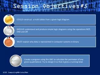
Binary Logic Starter: A lily pad doubles in size everyday. It takes 30 whole days to fill up the whole pond, how many days did it take to fill half the pond? Prove your answer...
Binary Logic We know that from von Neumann and the principle that all modern computers, data and instructions are based on the binary system (base 2). This is due to the ease in which 2 states can recognised – 0 and 1, on and off, true or false – by using simple transistors and capacitors. transistor capacitor Memory uses very small transistors and capacitors which can be linked together to make simple logical calculations: e.g are both inputs 1? or is only one input 1? These simple circuits are called Logic Gates.
Logic Gates There main gates are as follows: 1. NOT gate – it outputs the opposite of the input i.e input = 1, then output = 0, and vice versa. Truth Tables are used to express the relationship between input and output. (Algebraic values are used, ABC etc for input and PQR for output) Input Output
Logic Gates 2. AND gate – this tells us if both inputs are 1 by outputting 1, otherwise the output will be 0 e.g 3. OR gate – shows that either 1 OR 2 inputs are on by outputting 1, otherwise output is 0. e.g
Logic Gate Diagrams Each gate is represented by a different symbol: NOT gate AND gate OR gate INPUT OUTPUT
Logic Circuits Logic gates can be joined together to make more complex logic circuits. A common combination is the NAND circuit (Not AND) which frustratingly is a AND followed by a NOT gate. Similarly a NOR is an OR followed by a NOT. NAND – basically toggles the AND so that if both inputs are 1 then 0 will be output, otherwise 1 is output. Output R Output P
Logic Circuits This example has 3 inputs, 2 in the AND (A&B), outputting to an OR at P, and 1 directly into the OR. The resulting truth table is calculated: P
Boolean Algebra These logic circuits can be written down using mathematical expersions called Boolean algebra (named after Mathematician George Boole). i.e Q = (A AND B) OR C TASKS – Draw logic circuits and truth tables for the following P=NOT(A AND B) P=NOT(A OR B) P=A AND NOT (B) A AND NOT(B OR C)
Boolean Programming Boolean algebra is used in programming to perform many instruction. For example IF statements and While loops IF x >10 then... ELSE.... __________________ WHILE x < 10 AND NOT (end of file) DO Now try some simple programming using Ifs and Loops in Yousrc.