Download
1 / 22
250 likes | 438 Vues
Subsurface Environmental Characterization, Modeling, Monitoring and Remediation. Thomas J. Nicholson and George Powers Office of Nuclear Regulatory Research March 11, 2009 Regulatory Information Conference Rockville, Maryland. Session Issues.

E N D
Subsurface Environmental Characterization, Modeling, Monitoring and Remediation Thomas J. Nicholson and George Powers Office of Nuclear Regulatory Research March 11, 2009 Regulatory Information Conference Rockville, Maryland
Session Issues • Development of Alternative Conceptual Site Models • Characterization of Sources and Subsurface Processes • Integrated Monitoring and Modeling Programs • Risk-Informed Analysis Using Site-Specific Data • Decision Whether to and How to Remediate • Performance Monitoring to Evaluate Remediation Effectiveness 1
Speakers & Panelists Speakers: Robert Ford, Environmental Scientist EPA, Office of Research and Development, Cincinnati, OH Vince Adams, Director DOE, Office of Ground-Water and Soil Remediation, Germantown, MD Sean Bushart, Senior Program Manager EPRI, LLW Chemistry & Radiation Management, Palo Alto, CA Panelists: Stephen Cohen, Team Leader, New Facility Licensing U.S. NRC, FSME, DWMEP, DURLD Richard Raione, Branch Chief, Hydrologic Engineering Branch U.S. NRC, Office of New Reactors, DSER Mark Roberts, Senior Health Physicist U.S. NRC, Region I, DNMS, Decommissioning Branch 2
Conceptual Site Hydrologic Model Important to characterize the following: • Natural and engineered features, structures, backfills and soil-rock interfaces, boundary conditions and time-dependent processes • Potential sources of accidental, incidental and regulatory releases • Regional and site hydrologic setting (aquifers, surface- water bodies, springs, wetlands and drainage systems) and relationships • Local drinking water sources (ground- and surface-water sources) • Existing ground-water wells and monitoring points onsite and offsite • Depth to the water table and surface-water body elevations • Historical details on contaminant releases • Ground-water gradients, flow directions and velocities Once surface and/or subsurface contamination is detected, evaluate its significance and develop an appropriate response 3
Back-Up Slides for Panel Discussion Detailed discussions and illustrations follow on: • Conceptual Site Models • Characterization • Monitoring • Modeling • Remediation • NRC Information Sources 4
The Conceptual Site Model • Hypothetical representation of the site • Select, organize and communicate information • Subject to testing with new characterization and monitoring data Conceptual cross-section for the Rocky Flats Facility (Modified from K-H, 2004) 5
Uncertainties in Conceptual Models Sources of Hydrogeologic Uncertainty: • Incomplete knowledge of the subsurface system • Measurement error in characterizing the system’s features, events and processes (FEPs) • Natural variability in the system’s spatial properties, temporal events and transient external stresses • Disparity in scales of sampling, monitoring and simulation relative to actual dimensions of the FEPs • Parameter estimation • Scenario definition 6
Conceptual Model of a Complex Site from Ward et al. (1997) after Caggiano et al. (1996) 7
Site-Specific FEP’s for Developing Alternative Conceptual Site Models • Pathways for rapid spread of leaking contaminants • pipe or cable trenches • gravel backfill • May drive contaminants in directions not predicted by contouring a few data points on a water-table map • Local precipitation drainage (roof and storm drains) • Water-sources of leaks • can inject large amounts of water into the vadose zone, sometimes creating perching • drive ground water and contaminants in directions not predicted based on water levels from scattered monitoring wells GPR Images 8
Case Histories - Brookhaven Regional Ground-Water Flow Regional Geologic Setting Tritium Plume Plan Map Tritium Plume Cross-Section 9 Site Ground-Water Flow
Synthesis of CSM & Flow and Transport Models • AES developed a CSM that incorporated influence of nearby pumping wells and 3-D visualization of data • Used flow and transport modeling to validate that our CSM reflected observed monitoring data. (Modeling was done in Excel, MODFLOW under the GMS umbrella) • Once validated, used flow and transport modeling to evaluate remediation alternatives 10
Case Histories – Amargosa Desert Research Site (ADRS)Facility Characterization and Monitoring Data • Extensive USGS information on: • Monitoring well data from existing wells • Schlumberger resistivity soundings • Soil gas data • Thermocouple psychrometer data • Neutron probe data • Vegetation tritium analytical data • Analysis of this data suggested a fault which acted as a preferential transport path • Geophysical borehole log data (neutron-moisture, natural gamma, and gamma-gamma) • Analysis of characterization and monitoring data • Re-evaluation and compilation of existing data resulted in the identification of a potential preferential pathway in the unsaturated zone termed the Southern Structural Offset 11
Approx. LLRW disposal trench location ADRS Conceptual Site Model • Basis for the CSM: • Geology • Ground-water flow • Contaminant transport UZB-2 3-D resistivity block model of ADRS. 12
Synthesis of CSM & Flow and Transport Models • USGS had an existing CSM; however tritium modeling results did not match observed contaminant distributions. • AES developed an alternative CSM that included this fault. Observed data matched flow and transport simulations • Modeled resistivity data in 3-D using kriging through HydroGeo Analyst 2.0 Simple Excel spreadsheet model to simulate movement of tritium in vadose zone both laterally and vertically in response to proposed fault • Contoured tritium in ground water and vadose zone using Surfer code • Current CSM did not match movement of tritium in vadose zone • Revising CSM • An alternative CSM was proposed • Subsequent flow and transport modeling of the vadose zone produced results that more closely matched observed data 13
WHAT: • PI Recommendations • Class 1: tritium concentrations in ground water, soil gas, and plants • Class 2: vadose zone water flux • Class 3: incongruous water table shape, modeling congruity, tritium as outliers in ground water • Analysis of Site and Facility Characterization & Monitoring Data • Geophysical borehole log data (neutron-moisture, natural gamma, and gamma-gamma) • Monitoring well data from existing wells • Schlumberger resistivity soundings • Soil gas data • Thermocouple psychrometer data • Neutron probe data • Vegetation tritium analytical data • Analysis of this data suggested a fault which acted as a preferential transport path • Synthesis of CSM & Flow and Transport Models • USGS had an existing CSM; however tritium modeling results did not match observed contaminant distributions. • AES developed an alternative CSM that included this fault. Observed data matched flow and transport simulations • Modeled resistivity data in 3-D using kriging through HydroGeo Analyst 2.0 Simple Excel spreadsheet model to simulate movement of tritium in vadose zone both laterally and vertically in response to proposed fault • Used Surfer for contouring tritium in ground water and vadose zone PERFORMANCE CONFIRMATION MONITORING: Data Collection & Analysis • WHERE & WHEN: • Monitoring Points (MP) Recommendations: • Add vadose zone wells or CPTs near proposed fault to evaluate tritium and barometric pressure • Ensure site monitoring system is integrated and comprehensive • FEEDBACKbased on analysis of PCM data will be used to update CSM • HOW: • Monitoring Devices (MD) • Soil vapor, ground water sampling 14
Integrate Modeling with Monitoring Why monitor and model? Characterize natural and engineered systems: • Collect information to identify significant Features, Events and Processes • Develop and evaluate site conceptual models • Guide data collection including monitoring, sampling and geophysical surveys 15
Integrate Modeling with Monitoring Site-Specific Modeling Benefits: • Integrates disparate characterization and monitoring data into a logical framework • Reduces uncertainties and help to identify location of monitoring to confirm hydrogeologic system behavior • Forecasts impacts (doses due to exposure and uptake) • Provides bases for decision-making on the need to interdict, mitigate and remediation abnormal releases • Assists in designing and monitoring remediation program (e.g., monitored natural attenuation thru pump-and-treat) • Communicates understanding of the system to the public and facilitates technical interactions 16
1 NUREG/CR-6948 ANALYSIS: Site and Facility characterization & monitoring data Conceptual Site Model (CSM) Flow, transport Site modeling (PA) WHAT: Performance Indicators (PI) PERFORMANCE CONFIRMATION MONITORING: Data Collection & Analysis WHERE & WHEN: Monitoring Points (MP) HOW: Monitoring Devices (MD) • FEEDBACK to update: • CSM • PA • Choice of PIs, MDs, and MPs • Stopping Rules 17
Information Source – NUREG/CR-6948 • Technical bases for developing guidance on ground-water monitoring for NRC-licensed sites • Systematic methodology to integrate monitoring with modeling • http://www.nrc.gov/reading-rm/doc-collections/nuregs/contract/cr6948/v1/index.html 18
Information Source – NUREG/CR-6948 • Lessons-Learned for developing guidance on ground-water monitoring for NRC-licensed sites • Case Studies which includes Brookhaven radionuclide plume remediation and monitoring • http://www.nrc.gov/reading-rm/doc-collections/nuregs/contract/cr6948/v2/index.html 19
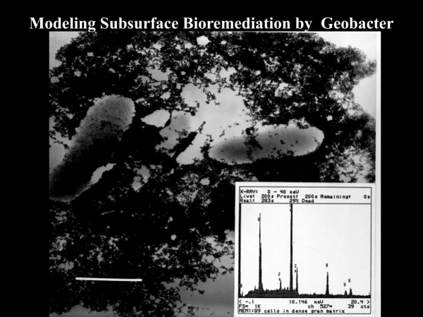
Information Source – NUREG/CR-6973 • Overview of in situ uranium bioremediation which identifies and prioritizes field performance indicators for evaluating its effectiveness. • Performance indicators to be monitored and modeled are based on current biogeochemical understanding of uranium. • Confirmation monitoring is vital to demonstrating long-term success of U-bioremediation and provides a significant assurance that regulatory goals will be met. • http://www.nrc.gov/reading-rm/doc-collections/nuregs/contract/cr6973/index.html 20
RES Studies in Support ofGround-Water Monitoring and Modeling • Assess contaminant transport in soils using ARS’s extensive field databases to identify and demonstrate model abstraction techniques, and assess uncertainties (NUREG/CR-6884) • Test PNNL Uncertainty Methodology at Hanford 300-Area to identify and quantify conceptual model, parameter and scenario uncertainties (NUREG/CR-6940) • Apply USGS surface-complexation models of U adsorption and retardation using field data from the Naturita Site (NUREG/CR-6820) • Assess the efficacy of in situ bioremediation to sequester U through monitoring and modeling of Performance Indicators (PNNL-17295) • Apply AES’s “Integrated Ground-Water Monitoring Strategy for NRC-Licensed Facilities and Sites” (NUREG/CR-6948) 21