Automobile Gearbox
1.69k likes | 4.25k Vues
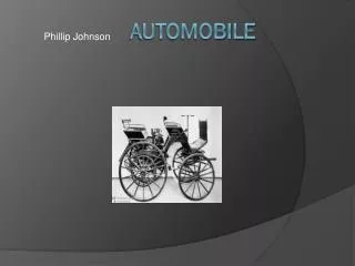
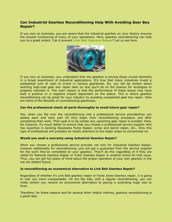
Automobile Gearbox . BY: GAURANG PRAJAPATI. The word “Transmission”. The word transmission means the mechanism that transmits the power from the engine crank shaft to the rear wheels. Function of Transmission.

Automobile Gearbox
E N D
Presentation Transcript
Automobile Gearbox • BY: GAURANG PRAJAPATI
The word “Transmission” • The word transmission means the mechanism that transmits the power from the engine crank shaft to the rear wheels.
Function of Transmission • Provide a means to vary torque ration between the engine and the road wheels as required. • Provides a neutral position. • A means to back the car by reversing the direction of rotation of the drive is also provided by the transmission.
Gear Ratio The gear ratio, or velocity ratio, between a pair of gear wheels is in inverse ratio to the number of teeth on each.
Gear Ratio Thus, NB/NA = DA/DB= nA/nB NB = NA (nA/nB)
Gear Ratio Where: NA= rev per min of gear A, nA = number of teeth on A NB = rev per min of gear B, nB = number of teeth on B DA = Diameter of gear ADB = Diameter of gear B
Types of Gearbox • Sliding mesh gearbox • Constant mesh gearbox • Synchromesh gearbox • Epicyclic Gearbox
Sliding mesh type gearbox • Constant mesh gears. • Primary shaft (Clutch shaft) • Spigot bearing. • Main shaft. • Lay shaft (counter shaft)
Sliding mesh type gearbox Primary shaft • This shaft transmits the drive from the clutch to the gearbox . • At the end, the shaft is supported by a spigot bearing positioned close to the splines on to which the clutch driven plate is connected.
Sliding mesh type gearbox Primary shaft • The main load on this shaft is taken by a bearing; normally a sealed radial ball type, positioned close to an input gear called a constant mesh pinion.
Sliding mesh type gearbox Primary shaft • The gear is so named because it is always in mesh with a larger gear • Small driving gear is called a pinion and a large gear a wheel.
Sliding mesh type gearbox Layshaft • This shaft, which is normally fixed to the gearbox casing, supports the various-sized driving pinions of the layshaft gear cluster
Sliding mesh type gearbox Main Shaft • This splined output shaft carries spur gearwheels that slide along the shaft to engage with the appropriate lay shaft gears. • At the ‘front’ end, the main shaft is supported by a spigot bearing situated in the centre of the constant mesh pinion.
Sliding mesh type gearbox Main Shaft • A heavy duty radial ball bearing is fitted at the other end to take the force of the gears as the attempt to move apart.
Sliding mesh type gearbox • The power comes from the engine to the clutch shaft and thence to the clutch gear which is always in mesh with a gear on the lay shaft. • All the gears on the lay shaft are fixed to it and as such they are all the time rotating when the engine is running and clutch is engaged.
Sliding mesh type gearbox Gear position
Sliding mesh type gearbox Neutral • All main shaft gearwheels are positioned so that they do not touch the layshaft gears. • A drive is taken to the layshaft, but the mainshaft will not be turned in neutral position
Disadvantage of Sliding mesh Gearbox • Gear noise due to the type of gear. • The difficulty of obtaining a smooth, quit and quick change of gear without the great skill and judgment.
Selector Mechanism • A fork is used to slide a gearwheel along the main shaft in order to select the appropriate gear. • It is mounted on its own rod and links the driver’s gear stick to the sliding gearbox.
Selector Detent • It holds the gears and selectors in position and so prevent gear engagement or disengagement due to vibration. • The figure shows a typical arrangement suitable for a layout having the selector fork locked to the rod
Interlock Mechanism • Prevents two gears engaging simultaneously • If this occurs the gearbox will lock up and shaft rotation will be impossible.
Power take-off arrangement • In addition to the mechanism use for driving a vehicle along a road, a power supply is often required for operating external items of auxiliary equipment. • A light truck having a tipping mechanism is one example, but the most varied application of power take-off units is associated with specialized off-road vehicles
Constant mesh gearbox • All the gear are in constant mesh with the corresponding gears on the layshaft. The gears on the splined main shaft are free • The dog clutch are provided which are free to slide on the main shaft. • The gears on the lay shaft are fixed.
Constant mesh gearbox • When the left dog clutch is slid to left by means of the selector mechanism, it’s teeth are engaged with those on the clutch gear we get the direct gear.
Constant mesh gearbox • The same dog clutch when slid to right makes contact with the second gear and second gear and second gear is obtained. • Similarly movement of the right dog clutch to the left result in low gear and towards right in reverse gear.
Double Declutching with Constant mesh Gearbox • For the smooth engagement of the dog clutches it is necessary that the speed of the clutch shaft, layshaft and main shaft gear must be equal. • Therefore to obtain lower gear, the speed of clutch shaft, layshaft and the main shaft gear must be increased. • By Double declutching this can be done.
Double Declutching with Constant mesh Gearbox • The clutch is disengaged and the gear is brought to neutral. • Then the clutch is engaged and accelerator pedal pressed to increased the speed of the main shaft gears.
Double Declutching with Constant mesh Gearbox • After this the clutch is again disengaged and the gear moved to required lower gear and the clutch is again engaged. • As the clutch is disengaged twice in this process, it is called double declutching
Advantage of Constant mesh Gearbox compared to Sliding mesh Gearbox • As the gear remain always in mesh, it is no longer necessary to use straight spur gear. Instead helical gear is used which are quieter running.
Advantage of Constant mesh Gearbox compared to Sliding mesh Gearbox • Wear of dog teeth on engaging and disengaging is reduced because here all the teeth of the dog clutches are involved compared to only two or three teeth in the case of sliding gears.
Synchromesh Gearbox • Similar to constant mesh type, because all the gears on the main shaft are in constant mesh with corresponding gears on the layshaft. • The gears on the main shaft are free to rotate on it and that on the layshaft are fixed to it.
Synchromesh Gearbox • Avoids the necessity of double declutching. • The parts which ultimately are to be engaged are first brought into frictional contact which equalizes their speed, after which these may be engaged smoothly.
Synchromesh Gearbox • A :engine shaft. • Gears B,C,D,E are free on the main shaft and always mesh with corresponding gears on lay shaft. • Members F1 and F2 are free to slide on splines on the mainshaft. • G1 and G2 are ring shaped members having internal teeth fit onto the external teeth on members F1 and F2 respectively.
Synchromesh Gearbox • K1 and K2 are dog teeth on B and D respectively fit onto the teeth of G1 and G2. • S1 and S2 are the forks. • T1 and T2 are the ball supported by springs. • M1,M2,N1,N2,P1,P2,R1,R2 are the frictional surfaces.
Synchromesh Gearbox • T1 and T2 tend to prevent sliding of members G1(G2) on F1(F2). • When force applied on G1(G2) through forks S1(S2) exceeds a certain value, the balls are overcome and member G1(G2) slides over F1(F2). • There are usually six of these balls symmetrically paced circumferentially in one synchromesh device.
Engagement of direct gear in Synchromesh Gearbox Cones M1 and M2 mate to equalize speeds. Member G1 pushed further to engage with dog k1
Engagement of direct gear in Synchromesh Gearbox • For direct gear, member G1 and hence member F1 is slid towards left till cones M1 and M2 rub and friction makes their speed equal. • Further pushing the member G1 to left cause it to override the balls and get engaged with dogs k1. • So the drive to the mainshaft is direct from B via F1 and the splines.
Engagement of direct gear in Synchromesh Gearbox • Similarly for the second gear the members F1 and G1 are slid to the right so that finally the internal teeth on G1 are engaged with L1. • Then the drive to mainshaft will be from B via U1, U2, C, F1 and splines. • For first gear, G2 and F2 are moved towards left • The drive will be from B via U1, U3, D, F2 and splines to the main shaft.
Engagement of direct gear in Synchromesh Gearbox • For reverse, G2 and F2 are slid towards right. • In this case the drive will be from B via U1, U4, U5, E, F2 and splines to the main shaft.