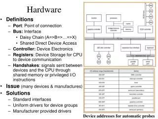
Download
1 / 34
340 likes | 455 Vues
This presentation discusses the status and measurements of the CBM Silicon Tracking System, including I-V and C-V setups, LabVIEW programs, and results from simulations and hardware setups. Key topics include TCAD simulation packages, SPICE simulation needs, and future plans for sensor prototypes and simulation parameters. Challenges in measuring resistance and capacitance after radiation damage are addressed, highlighting the importance of electrical parameter characterization and the development of radiation-hard silicon sensors for high-performance tracking in heavy-ion research.

E N D
Device Simulations & Hardware Developments for CBM STS Sudeep Chatterji CBM Group GSI Helmholtz Centre for Heavy Ion Research CBM Collaboration Meeting, Split, Croatia 6 October, 2009
Outline • Status last time • Measurements • I-V and C-V setup • labview programs • Results on some devices • Simulations • SYNOPSIS TCAD packages • Some results • SPICE simulation (What’s the need) • Next Sensor prototype from CIS • Future Plans
Status last time (Simulations) • Were Simulating Single sided strip detectors • Using PISCES and SUPREM
Status last time (Measurements) • Procured LCR meter
HV Isolation Box for LCR meter RC High Pass Filter • Purpose: • The leakage current can only flow through PA, no other path is allowed. • The AC signal sourced by LCR meter goes in DUT and then is sunk by LCR. • The operation of LCR and PA are decoupled. • Realisation: • The HV side of DUT is coupled via a blocking capacitor to H connector. • A large R prevents the AC signal sourced by H to be sank by power supply. • L conn. needs to be decoupled so that leakage current does not reach LCR.
Effect of open calibration open probe wires Before Calibration After Calibration
C-V characteristic of a 56pF capacitor with open calibration
I-V characteristic of a 91kOhm resistor (reverse bias voltage)
I-V characteristic of a 1N4151 p-n diode Reverse Bias Forward Bias (current limit 2.5mA)
Coupling Capacitance (CAC) • Typicalvalue ~ 100 pF • To avoid significant signal loss
Interstrip Capacitance (Cint) • Typical value ~ 1-10 pF • Purpose: To determine cross talk, Contributes to ENC • Cint = 2 (Cint1 + Cint2) • CTot = Cb + Cint • ENC = a + b.CTot e-/pF
Bias Resistor • Typical Value ~ 1-10 MΩ • Provides isolation between the strips • Rint is fine if the measured resistance Vs. VBias plateaus • The plateau level resistance is the Polysilicon bias resistance
Interstrip Resistance (Rint) • Typical Value ~ 1-10 GΩ • Provides isolation between the strips
Flat Band Voltage • Used to extract the surface oxide charge (Quality of Oxide) • Important parameter for surface radiation damage • Need to probe MOS device for this measurement
Need of new Measurements (SPICE Model) • The noise of the readout is determined by CTot seen by the preamplifier • Not only the Capacitance (C) but also the resistance (R) values affect signal • processing and various sources of noise. • It is not possible to measure all the R and C especially after irradiation • Radiation damage also induces variation in the macroscopic parameters, • such as resistance and capacitance values.
Need of new Measurements (SPICE Model) • R and C that could not be measured are treated • as free parameters in SPICE model and are • extracted through the fitting procedure. • Some parameters could be measured but could • not reach a plateau value with frequency
Measurement Table • Resistance of the implantation strip (Rn) can not be measured and Cnb and Cnn+1 measurements do • not have a plateau value. These were determined through SPICE simulations.
Summary/Future Plans • TCAD simulation running successfully (on batch farm) • Plan to start SPICE simulation (P-SPICE installed) • Decide with CIS the simulation parameters • Radiation Damage in DSSDs (help needed from Physicists) • In hardware, plan to carry out full sensor characterization • Design Probe card and Multiplexer (or explore market) • Irradiation of Sensors/Annealing studies • Accepted in 2009 IEEE NSS: • Development of Radiation hard Silicon Sensors for the CBM Silicon Tracking System using simulation approach - Oral • The Silicon Tracker of the CBM Experiment at FAIR: Detector Developments and First in-beam Characterization-Poster