Download

1 / 11
110 likes | 224 Vues
This system enables accurate measurement of beam phase and intensity in particle accelerators, ensuring precise monitoring and control. It features advanced components such as BPMs, button feedthroughs, and liquid helium cooling for optimal performance.

E N D
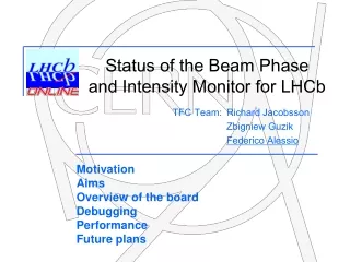
Beam phase and intensity measurement Grzegorz Kasprowicz Richard Jacobsson
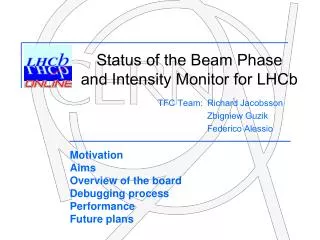
BPMs Button Feedthrough Beam Screen Liquid Helium Cooling Capillary
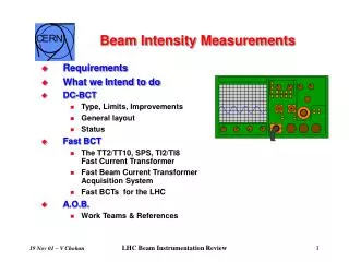
~150m to the IP Pick-ups at IPs (BPTXs) • Located ~150m from the IP in front of the D2 Magnet • One BPTX either side of the IP on the incoming beam • Exclusively used by the experiments • Monitoring phase of the beam with respect to LHC clock • Monitoring bunch intensity
Amplitude (V) Time (ns) BPTXs • Use Button Electrode BPM type • Peak voltage (one button) of ~5V after 200m of cable for nominal bunch • Sum voltage from all buttons Independent of beam position • Acquisition and processing?
BPIM specifications: M - Measuring beam intensity C - Collecting intensity results per bunch and averaging them - - Outputting intensity measurement at 40 MHz via LVDS interface - - Resolution of intensity measurement - 8 bits - - Measuring phase between incoming bunch signal and bunch clock - - Collecting delay results for every bunch and averaging them - - Digital approximation of converter characteristics - - Resolution of phase measurement better than 50ps - - Data processing in FPGA - Ethernet based control interface - - All the adjustments via the Ethernet - 6U VME board
Beam intensity measurement L` FPGA ADC Coefficients RAM LPF Linearization Block Result 40MB/s Pulse detect Delay Line 1 Delay Line 2 Histogram Calculation Block Threshold RAM Credit Card PC Glue Card Local Bus Ethernet
Beam phase measurement FPGA Coefficients RAM LPF Pulse detect Threshold Linearization Block Flip Flop ADC 12 bit BCLK Histogram Calculation Block Delay Line 3 Delay Line 4 RAM Credit Card PC Glue Card Local Bus Ethernet
Simulation results – beam intensity measurement rectified input signal integrator’s output ADC sampling moment input signal
Simulation results – beam phase measurement input signal integrator’s output D flip-flop output BCLK ADC sampling moment rectified input signal
Approximation A first order polynomial approximation is used All ADC range (0 to 4095) is divided into 32 sub ranges In each of them, measured value is described by equation: Ym = a*Xreal + b where Xreal – real measured value, Ym – measured value with error, a – scaling coefficient, b – shift value In order to obtain a real value, circuit must realize following equation : Xreal = (Ym – b) / a Implementation of this needs only one multiplier and adder