Stratos
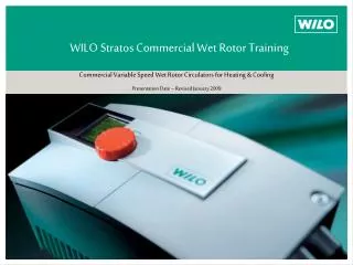
WILO Stratos Commercial Wet Rotor Training. Commercial Variable Speed Wet Rotor Circulators for Heating & Cooling Presentation Date – Revised January 2009. Stratos. Stratos Training Road Map Links to Specific Training Topics. Basics – North American Models AC vs. ECM Motor Technology

Stratos
E N D
Presentation Transcript
WILO Stratos Commercial Wet Rotor Training Commercial Variable Speed Wet Rotor Circulators for Heating & Cooling Presentation Date – Revised January 2009 Stratos
Stratos Training Road MapLinks to Specific Training Topics • Basics – North American Models • AC vs. ECM Motor Technology • Installation (Position and Wiring) • Control Modes via Red Button • Inter Face Modules • Applications • Overload Protection and Diagnostics • Infra Red Monitor • Simulator
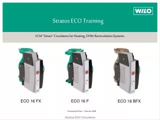
WILO Commercial Wet Rotor CirculatorsECM “Smart” Automatically Controlled Circulators • Stratos (Cast Iron Only) • ECM (Electronically Communicated) technology • Soft start high torque permanent magnet rotor • 8 Models available – interchangeable with Top S • Smart pump adjusts flow to system changes (∆p-v, ∆p-c and ∆p-t) • Temperature control for condensing boilers • Auto setback “fuzzy logic” • Non-volatile memory – no battery required • Standard industry flanges 1 ¼”, 1 ½”, 2” & 3” • Cataphoresis coating • Interface modules for 0-10Vdc, LON and external control • Dual pump mode (lead/lag, primary/secondary and back-up) • Infrared service/diagnostic tool available • Power consumption data logging • Ability to lock out red button • Single page start-up manual • 230 volt +/- 10%, single phase (2 x 115, 230/1, 230/3 all OK) • Overload protection (voltage, dry run, locked rotor, over temperature) • No external sensors • Class “A” energy rating
Stratos Features and Benefits • WILO Brain “Easy Read” Numbering System • References flange size and shut off heads @ min & max speed • Shortest “Lay Length” in the Industry (same size as Top S) • Industry Standard Flanges (all 2 bolt models are “commercial” type • 2 Bolt Oval for 1 ½” and 1 ¼” • Special “non - ANSI” 4 bolt for 2” • 125 # ANSI for 3” • Wet Rotor “Seal less” Design • Variable Speed • ECM Motor Technology (Electronic Commutated Synchronous Motor) • No Couplings • No Maintenance! • Automatically Vented • Fully Self Diagnostic • High and Low Voltage (min 183 volts, max 253 volts) • High Temp Motor or Electronics, Overload and Over current • Locked Rotor • Dry Run
Stratos Features and Benefits con’t • Ease of Selection – all Models 230/1/60 Volt (230/3 permissible) • Select Anywhere Between Min and Max Curves • LED readout in feet or meters (field adjustable) • Up to 80% Operating Cost Savings Due to ECM Technology • Permanent Magnet Rotor, Soft Start • 400% Increase in Starting Torque, 700% Increase in Bearing Life • Non-volatile Memory (power outages no problem – ever!) • Flexible Applications • Max System Temp 230 deg F (110 deg C), Min System Temp +14 deg F (-10 deg C) • Max inlet pressure 145 PSI – water and water/glycol up to 50% concentration • Simple Start Up (Infra Red Device Not Required) • Constant Pressure, Variable Pressure set via Red Button • Automatic Night Setback (enable or disable) • Adjustable Display • Interface Devices • LON, Vdc Remote Control and Dual Pump Operation • Infra Red Device (Sept 2007) • SD (Secure Digital) Interface (for use with PDA or Laptop) – Windows Based Software • Reads and monitors all pump outputs (pdf printouts)
Stratos “Return on Investment” • Contractors • Easy to install and set (one page start-up manual and overload protection • No pressure by-pass • No excessive pressure when last zone closes (noise and call backs) • Simplifies systems (fewer pumps and other accessories) • Quieter systems • Engineers • Single source responsibility • No external sensors • Allows for over pumping • Distributors • 8 models (all the same voltage) covers many models – fewer SKUs • Positions distributor as “Leading Edge” • Extremely flexible applications • LEED or Green Builders • Huge energy savings (constant speed circulators operate backwards) • ECM technology might qualify for subsidies • Part of LEED system
WILO Stratos Model Number System Stratos 1.5 x 3 - 40 • Stratos • 1.5 • Flange size in Inches • 3” ANSI, 125 # raised face, 4 bolt • 2” pump flange - 4 bolt “grooved” pump type • 1 ½” and 1 ¼” pump flange - oval 2 bolt “grooved” commercial type • 3 • Minimum head (ft) • 40 • Maximum head (ft)
Stratos North American ModelsAll Stratos are 230/1/60 Volt (230/3/60 OK – wire 2 of 3 leads) Stratos vs. Top S Interchangeability Stratos 1.25 x 3 - 20 & 25 (6 1/2”) Top S 1.25 x 15 & 25 Stratos 1.25 x 3 - 30 & 35 (8 1/2”) Top S 1.25 x 35 Stratos 1.5 x 3 – 40 (10”) Top S 1.5 x 20,30 & 40 Stratos 2.0 x 3 – 35 (11”) Top 2.0 x 25, 35 & 40 Stratos 3.0 x 30 & 40 (14”) Top S 3.0 x 25 & 50 (voltage?)
Stratos DocumentationOne Page “Quick Start” Manual and IF (Inter Face) Module Return to Index Catalogue Data Sheet (Detailed Info) Installation and Operation Manual WILO Stratos SubmittalStratos 1.25 x 3-30 WILO Stratos SubmittalStratos 1.25 x 3-30 Pump Dimensions Pump Dimensions Details Max Hp Pipe Size l0 l1 l2 a2 Weight Imperial 1/4 Hp 1 1/4” 8 1/2 4 1/4 2 3/16 1 7/8 19.8 lbs b1 2 1/2 b2 2 3/16 b4 4 3/16 b5 4 3/4 a1 8 Metric 200 Watt 32 mm 216 108 55 204 48 63 55 106 120 9.0 kg Details Max Hp Pipe Size l0 l1 l2 a2 Weight Imperial 1/4 Hp 1 1/4” 8 1/2 4 1/4 2 3/16 1 7/8 19.8 lbs b1 2 1/2 b2 2 3/16 b4 4 3/16 b5 4 3/4 a1 8 Metric 200 Watt 32 mm 216 108 55 204 48 63 55 106 120 9.0 kg Flange Dimensions Flange Dimensions Details Flange D d1 (dia) d2 Imperial 1 1/4 4 3/4 1 3/8 2 7/8 Metric 32 mm 121 35 73 k (dia) 3 1/2 89 n x dL 2 x 1/2 2 x 14 Details Flange D d1 (dia) d2 Imperial 1 1/4 4 3/4 1 3/8 2 7/8 Metric 32 mm 121 35 73 k (dia) 3 1/2 89 n x dL 2 x 1/2 2 x 14 Electrical Information Electrical Information Rated Power (P2) Hp max Speed Range Consumed Power (P1) watts min/max Amps 230/1 (and 230/3) Motor Protection 0.268 1600 - 4800 16 - 310 0.16 - 1.37 Integrated Rated Power (P2) Watts max 200 Rated Power (P2) Hp max Speed Range Consumed Power (P1) watts min/max Amps 230/1 (and 230/3) Motor Protection 0.268 1600 - 4800 16 - 310 0.16 - 1.37 Integrated Rated Power (P2) Watts max 200 Minimum Inlet Pressure Minimum Inlet Pressure 122 deg F (50 C) 203 deg F (95 C) 4.4 PSI 14.5 PSI 230 deg F (110 C) 23.2 PSI Operating Limits Temp Min/Max 14 to 230 Deg F (- 10 to +110 Deg C) Max Ambient Temp 104 Deg F (40 Deg C) Max Working Press 145 PSI (10 Bar) Materials of Construction Impeller Polypropylene (50% Glass Filled) Shaft Stainless Steel (X40 Cr13) Bearing Metal Impregnated Carbon Volute Cast Iron, Cataphoresis Coated Motor/Electronics Power Electronics Frequency Converter Degree of Protection Enclosure 2 Insulation Class H 122 deg F (50 C) 203 deg F (95 C) 4.4 PSI 14.5 PSI 230 deg F (110 C) 23.2 PSI Operating Limits Temp Min/Max 14 to 230 Deg F (- 10 to +110 Deg C) Max Ambient Temp 104 Deg F (40 Deg C) Max Working Press 145 PSI (10 Bar) Materials of Construction Impeller Polypropylene (50% Glass Filled) Shaft Stainless Steel (X40 Cr13) Bearing Metal Impregnated Carbon Volute Cast Iron, Cataphoresis Coated Motor/Electronics Power Electronics Frequency Converter Degree of Protection Enclosure 2 Insulation Class H Approval Stamp Here Approval Stamp Here Wilo USA LLC 1290 North 25th Avenue Melrose Park, Illinois 60160 Phone: 866 945 6872 Fax: 708 338 9455 Wilo Canada Inc Bay 7 - 2915 - 10th Ave N. E. Calgary, Alberta, T2A 5L4 Phone: 866 945 6236 Fax: 403 277 9456 Wilo USA LLC 1290 North 25th Avenue Melrose Park, Illinois 60160 Phone: 866 945 6872 Fax: 708 338 9455 Wilo Canada Inc Bay 7 - 2915 - 10th Ave N. E. Calgary, Alberta, T2A 5L4 Phone: 866 945 6236 Fax: 403 277 9456 www.wilo-na.com www.wilo-na.com
AC-motor Non controlled or VFD controlled pump Asynchronous-squirrel-cage motor Rotor is a sheet steel pack with nail like rods parallel to the rotor shaft The rotor movement is caused by the rotating stator magnetic field EC-motor WILO Stratos (and ECO) Brushless electronically commutated synchronous motor using a permanent magnet rotor The rotor magnetic field “grabs” the rotating stator magnetic field, causing rotor rotation Rotor (impeller) speed is determined by the pre-programmed drive software. EC-Motor Requires Controller Efficient – Comparrison AC- / EC-Motor
Smooth internalsurfaces Suction throat seal 3D-impeller Lip seal 3D-spirale volute Improving Hydraulic Efficiency • Engineering design of the Wilo-Stratos
Filter disc Filter plug Seal Improving Hydraulic Efficiency Return to Index Initial startup 1. Filling 2. Filtration 3. Lubricate 4. Air venting
Functional - Variable Mounting Positions • Mounting positions
Functional - Variable Mounting Positions Click Here to Play Video
All symbols for horizontal mounting. All symbols for vertical mounting. Functional - ‘Any Way‘ Positioned Display
Functional – Electrical Wiring Connections Click Here to Play Video
Functional – Electrical Wiring Connections • How to Wire • Stratos Technology Makes it Simple • Stratos Converts Power • Single Phase AC to DC • DC to Three Phase AC • Total Voltage 230 +/- 10% (208 OK) • 230 volt “hot” and neutral OK • Two 115 volt ‘hots” with no neutral OK • Wire from opposite sides of 115 volt panel • FC Fault Contact • Potential free, normally closed contact • Minimum contact load – 12 Vdc, 10 mA • Maximum contact load – 250 Vac, 1 Amp
Functional – Operating Control Via Red Button and Display Click Here to Play Video
Manual Control Mode • The manual control mode deactivates the control in the electronic module. • The speed can be manually adjusted to a preselected constant level • Adjustable in 10 RPM increments!
2 Constant speed pump H2 3 H1 Q2 Q1 Speed Control • Electronic continuous speed control (Constant Pressure) • Automatic differential pressure control 1. The „brain“ determined the actual pumping head. (actual value) nmax 2. The „drive“ sees the difference between the set value (point 1) and the actual value. (point 2) 3. Via ECM smart technology the controller reduces the speed and reduced the pumping head to match the system curve. (point 3) 1 Pumping Head H Ft Flow Q USGPM
Automatic Control Mode • Electronic continuous speed control • control modes • ∆p-c differential pressure constant • ∆p-v differential pressure variable (max head is twice min head) • ∆p-T temperature guided differential pressure control • ∆p-cv combination from differential pressure constant (second and third area of characteristic) and differential pressure variable (first area of characteristics) • Operation modes • Automatic night setback (let down function) • Manual regulation • DDC (Direct Digital Control)
H Saves energy, because the load-controlled pump adjusts to system changes Δpc Δpv Q Delta PC vs Delta PV Delta PC or Constant Pressure (differential) – low head systems Delta PV or Pressure Variant (max head twice min) – high head systems
Delta P-T Return to Index • Change in temperature at the pump changes the pressure setpoint • IR tool required to activate and set peramators • Stratos installed on return T Max: 150 F H @ Max T: 10’ T Min: 100 F H @ Max T: 30’ T Max: 190 F H @ Max T: 7’ T Min: 140 F H @ Max T: 25’ Head Head 25‘ 30‘ 7‘ 10‘ 140 F 190 F Temp 100 F 150 F Temp Non-Condensing Boiler Application (Decreases delta T on temp rise) Condensing Boiler Application (Increases delta T on temp rise)
Functional – Inter Face Modules • Front access (Face-to-Face) • Freely accessible wiring connections - NPT • Large terminal box • Plug-in IF-Modules
Functional – Inter Face Modules • External Min/0 – 10 Vdc/DP • 0 – 10 Volt DC External Input • Sets either pump speed or head set point (over rides electronic control) • Input resistance greater than 100k Ohm, Dielectric strength 24 V, Accuracy +/- 5% • External Minimum – potential free closed input terminals • Closed contact normal operation – open contact pump runs at min speed • Max contact load 24 Vdc/10mA, Dielectric strength 250 Vac • DP double pump terminals – hook up second (slave) pump • External Off/0 – 10 Vdc/DP (DP and 0 – 10 Vdc same as Ext Min) • External Off – potential free closed input terminals • Closed contact normal operation – open contact pump off (electronics on) • Max contact load 24 Vdc/10mA, Dielectric strength 250 Vac • SBM (run signal)/0 – 10 Vdc/DP (DP and 0 – 10 Vdc same as Ext Min) • RC Run Circuit remote sensing of pump operation • Closed contact normal operation – open contact pump off • Max contact load of potential free normally open contact – 24 Vac, 1 A
Functional – Inter Face Modules • LON interface for link-up to LONWORKS-networks, Transceiver FTT 10 A • PLR interface for link-up to BMS via über WILO-interface converter or onsite coupling modules • DP interface for an integrated dual pump management of 2 single-head pumps • Control input ‘ =...10V‘ for remote speed control orhead setpoint adjustments • Control input ‘Ext.Off‘ for volt-free normally closed contacts • Control input ‘Ext.Min‘ for volt-free normally closed contacts • Run signal SBM as volt-free normally open contacts Ext. Min Ext. Off Function Module type SBM LON PLR • • • • • • • • • • • • •
DDC Speed Control Mode • Remote speed adjustments n [RPM] 3.0 V = min. 1.5 V = Off n max 1.0 V = On, min. n min Off 1 1,5 3 10 Vdc
Remote Head Setpoint Control Mode • Remote setpoint adjustment H [ft] H max H min 1 10 Vdc
LON IF Module (Inter Face) • LON/DP • LON interface for LonWorks BMS building automations – FTT 10 A - LONTalk • DP double pump terminals – hook up second (slave) pump • Data points LON-Protocol • Pumps w/o external Sensor • Pump Setpoint • Requested Pump-Operating Mode • Pump Pressure • Pump Flow • Pump Speed • Runtime • Fault States of the Pump • Maintenance States • Fluid Temperature • Power Consumption in Watts • Power Consumption in Kilowatts • Energy Consumption • Control Mode for Normal Operation • Pumps with external Sensor additional • Remote Pressure-Sensor Input • Remote Temperature-Sensor Input • Remote Pressure-Sensor Minimum Value • Remote Pressure-Sensor Maximum Value • Remote Temperature-Sensor Minimum Value • Remote Temperature-Sensor Maximum Value
Double Pump (DP) Functions • All IF modules have the capability of connection/communication to one other Stratos (IF module required for both pumps). This enables dual control (master/slave) in parallel applications (both pumps must be the same size). Benefits include: • Dual pump energy management • Automatic alternation in the event of a failure (5 min delay) • Peak duty operation of both pumps when necessary (PC mode only) • Main/standby operation - 100% back up if sized accordingly • 24 hour run time alternation • Master/Slave function • On start-up both controllers flash “MA” • Press in either red button to set master • Slave pump follows adjustments made by master
Functional – Electrical Wiring Connections to Optional Modules Return to Index Click Here to Play Video
Application Drawings (Click immage to access „pdf“ drawings) Return to Index
Functional – Collective Fault Signaling (FC)FC is a Normally Closed Volt Free Contact for Remote Failure Sensing • The following faults will cause contact to open: • Over temperature motor • Over temperature control module • Over current • Pump shaft seizure • Short or grounding • Contact failure between motor and module • Power supply - undervoltage ( < 183 V ) • Power supply – overvoltage ( > 253 V )
Faults, Causes and Remedial Actions • Fault signals • If a fault occurs the pump is deactivated, the red fault LED in the IR-window (display left side) is on and the fault code is indicated on the display. • Following a 5-minutes interval the pump will be automatically re-activated. • The pump will only be switched off permanently after the 6th fault event of the same type. The fault must then be manually reset. • Note!Note exceptions E10 (locked rotor) and E25 (module contact failure). Here the pump will be switched off following the 1st fault event.
Faults, Causes and Remedial Actions • Warning signals • The fault will be shown on the display as a warning signal, however fault light and the SSM relay do not respond. • The pump continues operation the fault can occur repeatedly . • The indicated faulty operating condition should not be occurring over an extended period. • The cause must be attended to and be remedied. • Note!Note exceptions E04 and E05 (low or high voltage). These will be further processed as fault signals if these alarm signals remain activated for longer than 5 minutes.
Faults, Causes and Remedial Actions • Fault signals: Fault-LED “continuous light”
Faults, Causes and Remedial Actions • Fault signals: Fault-LED “continuous light”
Faults, Causes and Remedial Actions • Warning Signals: Fault-LED “off”
Faults, Causes and Remedial Actions Return to Index • Warning Signals: Fault-LED “off”
Functional - WILO-IR Monitor • Automatic communication – up to 16 pumps – 30’ Away • Manual coding not required • Always the right ‘wire‘ to the right pump.
Return to Index Functional - WILO-IR Monitor • PDA Specifications- Secure Digital I/O slot • Windows Mobile version 5 • Bluetooth for wireless printing • 300 Mhz CPU • 5 MB free memory • 64 MB ROM • 32 MB RAM • 240 x 320 pixel display
Training tools – Stratos Simulator Return to Index