Download
1 / 15
150 likes | 196 Vues
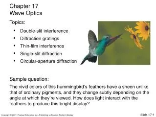
Learn about destructive vs. constructive interference, path length differences, and intensity distribution in diffraction patterns using Young's double-slit experiment and thin-film interference. Explore diffraction gratings, spectrometers, X-ray diffraction, and the unique properties of X-rays.

E N D
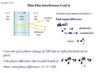
(Assume near-normal incidence.) Path length difference: destructive constructive where Thin-Film Interference-Cont’d • ray-one got a phase change of 180o due to reflection from air to glass. • the phase difference due to path length is: • then total phase difference: f = f’+180.
Young’s double-slit experiment • According to Huygens’s principle, • each slit acts like a wavelet. The • the secondary wave fronts are • cylindrical surfaces. • Upon reaching the screen C, the • two wave interact to produce an • interference pattern consisting of • alternating bright and dark bands • (or fringes), depending on their • phase difference. Constructive vs. destructive interference Two (narrow) slit Interference
Interference Fringes For D >> d, the difference in path lengths between the two waves is • A bright fringe is produced if the path lengths differ by an integer number of wavelengths, y ~ D*tan(θ)~ D*mλ/d • A dark fringe is produced if the path lengths differ by an odd multiple of half a wavelength, y ~ D*tan(θ)~ D*(m+1/2)λ/d
Intensity is proportional to E2 Intensity of Interference Fringes Let the electric field components of the two coherent electromagnetic waves be The resulting electric field component point P is then I=0 when f = (2m+1)p , i.e. half cycle + any number of cycle.
Phasor Diagram f2 f1
The superposition of wavelets can be illustrated by a phasor diagram. If the slit is divided into Nzones, the phase difference between adjacent wavelets is total phase difference: Phasor Diagram for Single-Slit Diffraction
central maximum because or Intensity Distribution 1 maxima: minima:
Intensity Distribution 2 for small q y • Fringe widths are proportional to /a. • Width of central maximum is twice any other maximum. • Width = D*λ/a – D*(-1)λ/a = 2D*λ/a • Intensity at first side maxima is (2/3)2 • that of the central maximum. • y ~ D*θ • Bright fringe: D*(m+1/2)λ/a • Dark fringe: D*mλ/a • Width: D*λ/a except central maximum
Light leaving each slit has a unique phase. So there is no superimposed single-slit diffraction pattern but only the phase difference between rays leaving the two slits matter. slit separation a where I0 is the intensity if one slit were blocked Young’s Double-Slit Experiment Revisited • Intensity pattern for an ideal double-slit experiment with narrow slits (a<<) • If each slit has a finite width a (not much smaller than ), single-slit diffraction effects must be taken into account!
double-slit intensity replace by single-slit intensity envelope Intensity Distribution from Realistic Double-Slit Diffraction
The diffraction pattern consists of a bright circular region and concentric rings of bright and dark fringes. • The first minimum for the diffraction pattern of a circular aperture of diameter dis located by geometric factor Rayleigh’s criterion Diffraction by a Circular Aperture • Resolution of images from a lens is limited by diffraction. • Resolvability requires an angular separation of two point sources to be no less than R where central maximum of one falls on top of the first minimum of the other:
D Types of gratings: • transmission gratings • reflection gratings up to thousands per mm of rulings Diffraction Gratings • Devices that have a great number of slits or rulings to produce an interference pattern with narrow fringes. • One of the most useful optical tools. Used to analyze wavelengths. Maxima are produced when every pair of adjacent wavelets interfere constructively, i.e., mth order maximum
Spectral Lines and Spectrometer • Due to the large number of rulings, • the bright fringes can be very narrow and are thus called lines. • For a given order, the location of a • line depends on wavelengths, so light waves of different colors are • spread out, forming a spectrum. Spectrometers are devices that can be used to obtain a spectrum, e.g., prisms, gratings, …
Standard gratings cannot be used as X ray spectrometers. (Slit separation must be comparable to the wavelength!) • Von Laue discovered the use of crystals as 3-dimensional diffraction gratings. Nobel 1914 X Ray Diffraction • X rays are EM radiation of the wavelength on the order of 1 Å, comparable to atomic separations in crystals. • X rays are produced, e.g., when coreelectrons in atomsare inelastically excited. They are also produced when electrons are decelerated or accelerated. • Vacuum tubes, synchrotrons, …