Download
1 / 6
60 likes | 180 Vues
This document outlines a methodology for optimizing the performance of an Analog-to-Digital Converter (ADC) system using a comparator and flip-flop logic. The process begins by detecting a rising edge, counting clock pulses before enabling the ADC, and ensuring timing integrity with a 1.25μs sampling period at 800 kcps. Key considerations include preventing system paralysis, managing data sampling cycles, and utilizing both coincidence and anti-coincidence comparisons. The approach integrates a peak-and-hold mechanism and offers task groups for adjustable gain, threshold voltage, sampling time, and coincidence handling.

E N D
Threshold Baseline Reset Reset Zoom-in After detecting rising-edge of comparator, count x (in this case 5) clock pulses, then enable ADC Assuming 800 kcps, the ADC takes 1.25 μs to sample Timing Diagram 1 horizontal unit = 5 clock cycles = 250 ns
Positive edge-triggered Count 5 clock cycles before starting ADC Reasons for a Flip-flop • Prevents system from paralyzing • A 2nd data sampling cycle can’t begin in the midst of the 1st • Anything else?
Coincidence/Anti-coincidence Comparator Synchronous Reset Asynchronous Reset Threshold Signal Gain Buffer PIC Mac USB Reset Peak and Hold 10 Block Diagram Peak Voltage ADC Enable
Coincidence/Anti-coincidence Comparator Fast Counter Reset Threshold Signal Gain Buffer PIC Mac USB Reset Peak and Hold 10 Peak Voltage ADC Enable
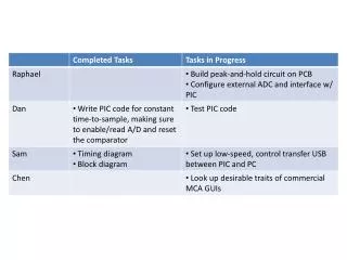
Group Tasks 4 Knobs 1) Input gain 2) Threshold voltage 3) Time-to-sample 4) Coincidence, anti-coincidence, and no coincidence • Test/fix the detector, pre-amplifier, and shaping-amplifier • Look at the pulses coming from the X-ray source