Download
1 / 19
190 likes | 311 Vues
This summary outlines the discussion surrounding various work packages for the Main Linac (ML) focusing on Quadrupole magnets and instrumentation needs. Key topics include the design and testing of superconducting quadrupoles, alignment requirements, and the integration of advanced beam instrumentation. Challenges such as reliability, performance specifications, and future R&D initiatives were identified. The document also addresses budget estimations and staffing requirements for effective execution of the project, ensuring that the installation process remains efficient and meets necessary technical standards.

E N D
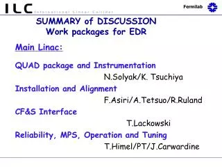
SUMMARY of DISCUSSION Work packages for EDR Main Linac: QUAD package and Instrumentation N.Solyak/K. Tsuchiya Installation and Alignment F.Asiri/A.Tetsuo/R.Ruland CF&S Interface T.Lackowski Reliability, MPS, Operation and Tuning T.Himel/PT/J.Carwardine
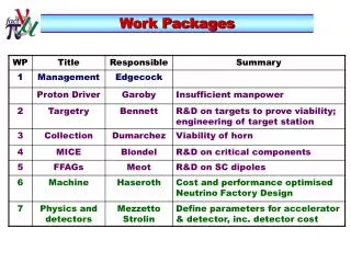
Magnet System Work Packages Magnet Work Packages Power System WPs • Incl. magnet interfaces to Controls System • Does not include Pulsed Magnets Magnet Facilities WPs • Separate special magnets from more ‘routine’ conventional designs • A separate WP for ‘pulsed magnets’ Cold magnet test facility design – shared with cryomod’s/SRF test & measurement systems
Main Linac Cryomodule Central support 300 mm pipe SCRF BPM Quadrupole and Corrector SCRF SC Quads /Correctors ~ 620 in Linacs + RTML
SC magnets for ML • Critical Component of the ML and RTML • Tight specification • Requirements for center stability ~1um • Small fringing fields in the cavity • No dipole-corrector coupling effects • No proven design yet • R&D and prototyping are needed to confirm the specified performance and efficiency • Number of magnet types (low/medium/high energy) • Combined or stand alone correctors • Optimal quadrupole configuration • Magnetic center stability during –20% field change • Sub-packages with high priorities (Low energy magnet)?
ART FY08/09 Budget proposal (2 Years) Target 2 Total: 0.75 FTE*year 0 M&S Total: 4.75 FTE*year 214 k$ M&S Total: 1.8 FTE*year 285 k$ M&S
Funding for FY08-FY09 was planned w/o EDR needs EDR SC magnet design and cost estimate cannot be carried out without sufficient funding EDR Magnet Design and Cost Effort Preliminary Staffing Estimate for “100% Design” Feb.07.02
SC Magnet development plan at KEK (K. Tsuchiya) • Budget and Manpower - dedicated test facility : ~1.5 M$ cooling system field measurement system - ~6 magnets : ~1.5 M$ - magnet installation into cryomodule ~ 0.3 M$ and test operation • Manpower magnet design & fabrication : 2.0 FTE/ year cooling system : 1.5 FTE/ year field measurement system : 1.5 FTE/ year (* Preliminary estimations)
Instrumentation Overview Beam instrumentation needs in the Main Linacs, as listed in the RDR: + Further R&D is required on the HOM coupler signal processing for beam orbit, cavity alignment and beam phase measurement! Work package proposal: M&S ~ 200 k$, FTE ~ 3 ManYears.
Instrumentation R&D packages desciption • L-band cavity BPMs (Linacs, RTML, BDS, both warm and cold ) • Cavity BPM • Analog and digital read-out electronics • Trigger/timing hardware to time-resolve position for individual bunches • A system for calibration and self-diagnosis tests. • Digital data acquisition and control hard/software, incl. interface. • Auxiliary systems (racks, crates, power supplies, cables, etc.) • Laserwire :(Linacs, RTML and BDS) • Laser (one can feed many IP’s) IP (multi-plane) • Distribution e /γ Separation • Deflector (scanner) Detector • Beam Feedback Systems • stabilize beam trajectories/emittance/dispersion in the Linacs. • Trajectory Feedback (several cascaded loops) - 5Hz • Dispersion measurement and control • Beam energy (several cascaded sections) (5Hz) • End of linac trajectory control (bunch-by-bunch)
Methodology- Assumption Installation time frame: Years Lab 8 Project management Years Lab 6 Project engineering Years Lab/ Contract 4 Cryomodule handling & shipping Cryomodule underground installation 3 Years Contract 250 Working days per year Contract 1668 Number of Main Linac Cryomodules Installation rate: Three Cryomodules per day * * 556 days @ max rate of Cryomodule installation, plus learning curve and interrupts. ML installation ~ 3 500 000 hrs F.Asiri
FUTURE PLANNING • There are a series of long lead items that must be addressed, before the installation can commence. These are: • Warehousing capacity • Tunnel transportation for equipment & personnel • Materials handling requirements for the tunnel • Utility requirements & locations including cryo box locations in the tunnel. • Data processing, including inventory control & scheduling.
Application of Virtual Design & Construction Technologies Job Site Fabricator Transporter Mobile Technology Mobile Server 4D Technology (3D CAD + schedule) Operation Optimization 4D model / interference check (NavisWorks) Integrated Central 4D Database (Enterprixe) Discrete event simulation (Strobscope) Scheduling (Primavera) 3D model (AutoCAD) Database Technology
FUTURE PLANNING • Installation G.S. • Goal: to produce an integrated Installation process for the ILC Baseline in full cooperation with other regions • Set-up and manage an installation data base in FY 07 that can be expanded in a full pledged program thru FY 08 and FY 09 • Estimate: FY 07;1.5 FTE and ~ $100K M&S (contract) FY 08; 2 FTE and ~ $200K M&S (contract) FY 09; 2 FTE and ~ $200K M&S (contract)
CF&S Effort Levels (before EDR) • The CF&S effort will need to ramp up sharply over the next three years in order to complete what we perceive is required for the EDR. • A parallel effort to develop regional selection documents will add to the EDR effort. • Regional support and funding is under discussion, but not firm enough to make financial commitments. • All regions have limited available in-house engineers. Will need to through expanding A&E consultants. 4M$ - 7M$ - 19M$ T.Lackowski
Firm #1 – General Architect/ Engineering Firm ($1,000K to $2,500K) • This firm will provide professional architectural and engineering services to support the ILC mission. The general scope of this work may include: • Condition Assessments; • Surface Building Programming: • Site Planning; • Building design; • Conceptual Design Studies and reports • Value Management Analysis Firm # 2 – Underground Engineering Expertise (at least three firms anticipated to be selected) ($5,000K to ($10,000K) • Design, cost estimating, and scheduling of hard rock tunnels, caverns and halls. • Design, cost estimating, and scheduling of soft rock tunnels, caverns and halls. • Design, cost estimating, and scheduling of open cut enclosures. • Conceptual Design Studies and reports • Presentation Drawings: • Value Engineering Analysis • Soil borings, and the associated field and laboratory analysis. Geotechnical Reports • Geotechnical baseline reports
Firm # 3 – Site Civil Expertise ($500K to $1,000K) • Firm # 4 Electrical Expertise ($300K to ($900K) • Firm # 5 Process Cooling and Mechanical Engineering ($600K to $1,200K) • Firm # 6 – Life Safety Engineer ($300K to $700K) • Firm #7 – Configuration Controls and Project Controls Systems ($400K to $1,200K) • Firm # 8 – Environmental, Safety and Health ($300K to $600K) • Firm # 9 – Land Acquisition Support ($200K to $500K)
Availability T.Himel • Description: • Monitor progress of other groups in meeting reliability goals. Aid them with simulations or calculations as requested. • Adjust reliability goals to minimize risk and cost as development continues • Keep availability model updated to changes in design. Add in more detail as necessary. • Should we set up a FMEA plan and get all systems to use it in the design of their parts? (not included in FTE estimate below) • What should we do about systems like water instrumentation, collimators, and coupler interlocks that need major MTBF improvements that don’t have ongoing R&D projects? • Resources: • 1 FTE level of effort through 2nd year of construction
MPS system: • 33 FTE level of effort through 5th year of construction • 2 FTE years for fault scenario simulations. Should be done in first 1.5 years of EDR as results could effect beam-line layouts • PPS +BCS: • 0.5 FTE level of effort through 2nd year of construction • 2 FTE-years of rad-physics calculations guided by above LOE person. Should take place in first 1.5 years of EDR as shielding may effect layout. • Refine alignment and vibration tolerances • 2 FTE years. MUST be done in 1st year of EDR so detailed magnet and support designs can be done based on the tolerances.
Tuning and feedbacks: • 12 FTE years if it is done 3 times so people are checking each other. Considerable computing resources will be needed hopefully these exist at the lab already and hence don’t count as M&S. This effort can start slow and can extend to the beginning of construction • Commissioning: • 0.2 FTE level of effort through end of the EDR • Then .5 FTE level of effort through 4th year of construction. • Some beam operations start in 3rd year of construction • 6 FTE years if everything is done once.