Download
1 / 25
250 likes | 264 Vues
This document discusses the work packages and priorities for the Engineering Design Report (EDR) of the Main Linac magnet systems and instrumentation. It covers the scope of the EDR, coordination challenges, funding mechanisms, and the organization of work packages. The document also provides details on the different magnet types and their specifications, including the quadrupoles for the Main Linac.

E N D
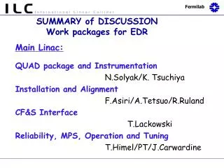
Main Linac Magnet Systems and Instrumentation Work Packages for EDR Nikolay Solyak, John Tompkins, Vladimir Kashikhin Graham Blair, Phil Burrows Marc Ross, Manfred Wendt Junji Urakawa N.Solyak
Guidance from R&D Board (Mark Ross) • What RD priorities are indicated by RDR cost? Are these different from ongoing priorities and efforts? Are the cost interactions of ACD known well enough to allow this prioritizations? • Is the RDR baseline cost estimate useful for this process or is more work needed simply to refine the RDR estimate in order to prioritize the RDR? Much of the RDR technical is ‘immature’. • How do the above interact with the design work now underway at DESY? • When is down-selection information needed? What is the latest ‘possible’ moment at which decisions can be taken that minimizes the disruption to the most effort intensive parts of EDR? • Each RD task can be categorized, based on the answer to item 4. How is this best done? • Each RD task will be funding limited, many severely. Are there some which will then necessarily come too late to be part of EDR? What does this mean for RD funding prioritization and for the EDR schedule? N.Solyak
The ILC EDR (Engineering Design Report) • What is it? • Detailed design report as basis for approval to proceed as a project • Scope • Early rumors: “~30% design level” • Sufficient detail to establish technical design package • Magnetic design (field, forces, heating, quench protection, etc… - calculations) • Define all interfaces – pedestals, stands, power, lcw, sensors, etc. • Develop accurate beamline layouts with real space allocations • Estimate of tooling requirements, design concepts • Sufficient information for detailed cost estimate N.Solyak
EDR Scope, cont. • Scope, cont. • Recent discussions: “complete design package” for all magnets • All R&D completed (models, prototypes tested) • Detailed design of all components completed • Tooling design completed • Drawing packages completed • Ready to begin procurement… • In either case, the resources required are a factor of ≈(3–10)x more than have been used in the RDR • Magnet physicist/engineers • Design/drafters • Tooling designers • Test stands, • Etc. N.Solyak
Organization • Independent Work Packages issued by Area Systems • Consistent with organization of RDR • What missing in this approach? Coordination • Management structure above Area Leaders still to be developed • Program/Project manage sought • Quasi-independence of work packages leaves some concerns on uniformity of approach, duplication of effort, “enforcement of standards” • There needs to be a work package for coordinating the Magnet Systems work: • Application of design standards-operational characteristics and availability/reliability? • Minimization of the number of individual magnet styles? N.Solyak
Work Package Organization, cont. • Funding mechanisms most likely to remain very similar to those at present • No significant ILC (i.e., area/country independent) funds • Funding through governmental agencies to laboratories and universities • No information about how funding for work packages might be structured • Could a work package be divided into sub-packages for groups from different areas? • Tiered work package management structure? N.Solyak
Magnets and magnet types at RDR TABLE. Numbers of conventional and SC Magnets in ILC Areas *Includes SC magnets in 12 additional CM’s in electron linac to compensate energy losses in undulator section + RTML SC magnets N.Solyak
Work Packages - a Magnet Systems View • Three distinct components • Magnets • Power Systems • Test and Measurement Facilities • Magnets and Power Systems divide among Area Systems in a natural fashion • Exception – pulsed magnet systems are still R&D intensive and have significant commonality across several areas; it is not sensible to split it up N.Solyak
Magnet System Work Packages Magnet Work Packages Power System WPs • Incl. magnet interfaces to Controls System • Does not include Pulsed Magnets Magnet Facilities WPs • Separate special magnets from more ‘routine’ conventional designs • A separate WP for ‘pulsed magnets’ Cold magnet test facility design – shared with cryomod’s/SRF test & measurement systems N.Solyak
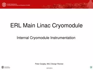
Main Linac Cryomodule Central support 300 mm pipe SCRF BPM Quadrupole and Corrector SCRF ILC TESLA TDR N.Solyak
Quadrupoles for Main Linac (TESLA) • ILC Main Linac Quadrupoles specs • Low current 50–100 A • Aperture 78 mm • Gradient 54 T/m • Length ~ 0.66 m • Adjustable field - 20% • Magnetic center stability better than 2 μm • Low fringing fields: 1/10μT cooldown/operat Possible issues: magnetic center motion fringing field trapped in SCRF CIEMAT quad will be tested at SLAC in 2007 Calculated 2-4 μm magnetic center displacement in quadrupole with dipole correctors because of superconductor magnetization N.Solyak
Dipole Correctors for Main Linac • Three versions of correctors: • Combined with main quadrupole (TESLA,CIEMAT) • Stand alone shell type dipoles+skew correctors • Stand alone window-frame type dipoles+skew correctors Proposal: 1. Separate main quadrupole and dipole correctors to eliminate coupling effects 2. Move quadrupole+corrector in space between cryomodules (Deferred) N.Solyak
Dipole Correctors Shell Type Window-Frame type Flux density and flux lines at max current in both dipole coils Field homogeneity at max current in both dipole coils (+/- 1% at R< 30mm) N.Solyak
Summary of preliminary magnet studies • Linac superconducting magnets are feasible • R&D and prototyping are needed to confirm the specified performance and efficiency • Main issues: • - Optimal place for quadrupole package (center, end or separate cryostat) • - Optimal quadrupole configuration • - Integrated field range (high:low) • - Magnetic center stability during –20% field change • - Combined or stand alone correctors • - Fringing fields in SCRF areas from magnet package • - Effective current leads N.Solyak
EDR Magnet Design and Cost Effort Preliminary Staffing Estimate for “100% Design” 070202 * SC magnets include e+,e- sources, RTML, ML, BDS N.Solyak
ART FY08/09 Budget proposal Target 2 Total: 0.75 FTE*years 0 M&S Total: 4.75 FTE*years 214 k$ M&S Total: 1.8 FTE*years 285 k$ M&S N.Solyak
Now let’s get realistic… • Support for EDR (US view) • Funding for FY07 is already extremely difficult without adding EDR • Funding for FY08-FY09 was planned w/o EDR • Guidance is already below levels needed to carry out full R&D programs • Addition of EDR design effort is not at levels necessary to support even the “30% design” • EDR magnet design and cost estimate cannot be carried out without sufficient funding • Funding cannot compete with Area System R&D needs, it will always lose N.Solyak
Getting real, cont. • This is not the RDR cost estimate • Detailed drawings required • All external interfaces need to be determined • Magnet engineers, physicists, alignment engineers • Tooling designers • Design/drafters • Buyers (for estimates) • No estimates based on “engineering experience” • Drawing packages, ‘bills of materials”, etc., needed for estimates • Availability/reliability needs to be “designed-in” • FMEA studies must be conducted • Management expectations must be consistent with resources allocated to the task N.Solyak
Instrumentation Overview Beam instrumentation needs in the Main Linacs, as listed in the RDR: Further R&D is required on the HOM coupler signal processing for beam orbit, cavity alignment and beam phase measurement purposes! Work package proposal: M&S ~ 200 k$, FTE ~ 3 ManYears. N.Solyak
Instrumentation R&D packages • L-band cavity BPMs (Linacs, RTML and BDS, in both warm and cold sections) • Cavity BPM • A set of analog and digital read-out electronics • Trigger & timing hardware to time-resolve position for individual bunches • A system for calibration and self-diagnosis tests. • Digital data acquisition and control hard/software, incl. a system interface. • Auxiliary systems (racks, crates, power supplies, cables, etc.). • Laserwire :(Linacs, RTML and BDS) • Laser (one can feed many IP’s) • Distribution • Deflector (scanner) • IP (multi-plane) • e /γ Separation • Detector • Beam Feedback Systems • stabilize beam trajectories/emittance/dispersion in the Linacs. • Trajectory Feedback (several cascaded loops) - 5Hz • Dispersion measurement and control • Beam energy (several cascaded sections) (5Hz) • End of linac trajectory control (bunch-by-bunch) N.Solyak
Cold BPM & HOM R&D • DESY plans to use button-style BPM’s (~30…50 µm single bunch resolution) together with HOM-based signal processing (~ 5 µm macropulse resolution) for their XFEL project. • CEA-Saclay improves the read-out system for their resonant re-entrant cavity BPM to achieve ~ 1 µm single bunch resolution. • SLAC successfully tested their 35 mm aperture S-Band CM-free cavity BPM at the ESA (beam verified ~ 0.8 µm single bunch resolution) in a “warm” environment. • Fermilab develops a cold L-Band CM-free cavity BPM with integrated monopole mode normalization. • A FPGA-based HOM-signal processor is studied in collaboration between Fermilab, DESY and SLAC (and Daresbury Lab?). Further HOM signal processing techniques have to be developed for a high resolution beam phase detection. N.Solyak
S-band BPM Results N = 1.4*1010 electrons BPM_res = 0.8 micron, Q ~ 500 for clean bunch separation 36 mm ID 126 mm OD N.Solyak
Cold Cavity BPM R&D @ FNAL Window – Ceramic brick of alumina 96% = 9.4 Size: 51x4x3 mm N type receptacles, 50 Ohm, N.Solyak
Laserwire R&D • Laserwire R&D activities are an ongoing collaboration between Royal Holloway University of London, KEK and DESY. KEK-ATF extraction line laser wire IP single scan dimension • Laserwire basics: • Laser (one can feed many IP’s) • Distribution • Deflector (scanner) • IP (multi-plane) • e/γ Separation • Detector DESY-PETRA two scan planes N.Solyak
ART FY08/09 Budget proposal Target 2 Total: 3.25 FTE*year 270 k$ M&S N.Solyak