Wiring for CAN bus
270 likes | 645 Vues
Wiring for CAN bus. ATLAS DCS. Table of contents. ATLAS DCS. Introduction CAN standards Layout of a standard rack configuration Cable requirements Solutions proposed The rack monitoring board The simulation tool. Introduction. ATLAS DCS. Definition of our CAN bus application.

Wiring for CAN bus
E N D
Presentation Transcript
Wiring for CAN bus ATLAS DCS Sébastien Franz PH-ATI-DC Stéphane Detraz PH-ESS
Table of contents ATLAS DCS • Introduction • CAN standards • Layout of a standard rack configuration • Cable requirements • Solutions proposed • The rack monitoring board • The simulation tool Sébastien Franz PH-ATI-DC Stéphane Detraz PH-ESS
Introduction ATLAS DCS Definition of our CAN bus application Sébastien Franz PH-ATI-DC Stéphane Detraz PH-ESS
MAXIMUM CABLE LENGTH The limitation come from : • ELMB supply drop through cables • CAN supply drop through cables • CAN bus limitation (from signal point of view) Sébastien Franz PH-ATI-DC Stéphane Detraz PH-ESS
CAN BUS LIMITATION CAN bus length main limitations (from signal point of view) • Signal round-trip delay • Oscillator tolerance between nodes • Signal amplitude drop The two first effects are not discussed during this Presentation. However, as rule of thumb, the following bus line length can be achieved… Sébastien Franz PH-ATI-DC Stéphane Detraz PH-ESS
Bit rate / Bus length relation …with CAN bit timing parameters being optimized for maximum propagation delay! Sébastien Franz PH-ATI-DC Stéphane Detraz PH-ESS
CAN bus signal • Maximum number of nodes : The maximum number of nodes which can be connected to a network depends on the minimum load resistance a transceiver is able to drive : The PCA82C250 transceiver provide an output drive capability down to a minimum load of 45Ω… … which give a maximum number of 112 nodes for 120Ω termination! Sébastien Franz PH-ATI-DC Stéphane Detraz PH-ESS
CAN bus signal • Maximum bus line length Is given by the minimum differential voltage at the receiving node for a dominant bit level. A receiver recognizes a dominant bit if the differential voltage is above 1V. We can use the following diagram to calculate the maximum bus length. Sébastien Franz PH-ATI-DC Stéphane Detraz PH-ESS
CAN bus signal From the precedent diagram we can find the following formula : Whoua!! With : ρ is the cable linear resistance → 0.0375 Ω/m for NE06 Vdiff_out_min is the transceiver min. diff. output voltage for a dominant bit level → 1.5V Vth is the dominant state receiver threshold voltage → 1V VSM is a safety margin voltage which can be determined as : K*(Vdiff_out-Vth) With 0≤K≤1 e.g K=0.8 → 0.4V RT is the termination resistance → 120Ω Rdiff_min is the minimum transceiver differential input resistance → 20kΩ Nmax is the maximum number of node on the bus → let’s say 30 Sébastien Franz PH-ATI-DC Stéphane Detraz PH-ESS
CAN bus signal The result for NE06 cable & 30 nodes is : 111m! Sébastien Franz PH-ATI-DC Stéphane Detraz PH-ESS
Standard configuration ATLAS DCS Sébastien Franz PH-ATI-DC Stéphane Detraz PH-ESS
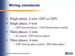
Cable characteristic impedance • The ISO 11898 CAN standard prescribes that the cable impedance be nominally 120Ω. But an impedance interval of 108 to 132Ω is permitted. Sébastien Franz PH-ATI-DC Stéphane Detraz PH-ESS
Cables datasheets • NG18 (SCEM : 04.21.52.218.9) • NE06 (SCEM : 04.21.52.110.0) Sébastien Franz PH-ATI-DC Stéphane Detraz PH-ESS
Cable propagation delay • Signal velocity in cable : Lossless lumped equivalent circuit Example : 2x0.5mm2 NE P cable L : 0.65µH/m C : 0.075nF/m V = 0.143m/ns Thus tp = 698ns for 100m [m/s] [F/m] [H/m] Sébastien Franz PH-ATI-DC Stéphane Detraz PH-ESS
Signal reflection • Example with 100m of 90Ω cable and 250 Kbaud CAN speed The bit duration is : 4µs The reflection duration : 1.4µs In this case (120Ω termination) : 1st reflection level : V1 = Vs*Ctl = Vs*1.143 (+14%) 2nd reflection level : V2 = Vs*Ctl*[1+Crl*Crs] = Vs*0.98 (-2%) 3rd reflection level : V3 = Vs*Ctl*[1+Crl*Crs+(Crl*Crs)2] = Vs*1.003 Ctl : load transmission coefficient Crl : load reflection coefficient Crs : source reflection coefficient Sébastien Franz PH-ATI-DC Stéphane Detraz PH-ESS
Signal reflection SUMMARY 0.47V margin 0.32V margin Signal wave form & noise margin Bounce diagram Sébastien Franz PH-ATI-DC Stéphane Detraz PH-ESS
Solutions proposed ATLAS DCS • The thick cable and connectors associated Sébastien Franz PH-ATI-DC Stéphane Detraz PH-ESS
Solutions proposed ATLAS DCS • The junction box Sébastien Franz PH-ATI-DC Stéphane Detraz PH-ESS
Solutions proposed ATLAS DCS • The thin cable and connectors associated Sébastien Franz PH-ATI-DC Stéphane Detraz PH-ESS
Solutions proposed ATLAS DCS • The prices for the thin cable : • The 3 twisted pairs cable: 1.60 CHF/m • Two single connectors (a male and a female): 18.31 CHF • One double connector : 34.61 € Sébastien Franz PH-ATI-DC Stéphane Detraz PH-ESS
Monitoring board CAN supply • Supply topology ELMB digital supply D-SUB 9 pins ELMB ADC supply HAVE TO BE REPLACED BY LOWER VALUE RESISTORS Sébastien Franz PH-ATI-DC Stéphane Detraz PH-ESS
Monitoring board TOTAL VAP+VDP = 59mA without Air flow 84mA with Air flow @ Ta=45°C Sébastien Franz PH-ATI-DC Stéphane Detraz PH-ESS
The simulation tool ATLAS DCS • The front panel Sébastien Franz PH-ATI-DC Stéphane Detraz PH-ESS
The simulation tool ATLAS DCS • Tests of the software Sébastien Franz PH-ATI-DC Stéphane Detraz PH-ESS
Some examples… ATLAS DCS Sébastien Franz PH-ATI-DC Stéphane Detraz PH-ESS
Conclusion ATLAS DCS • This design of the wiring will work without problem for our CAN bus applications. • Wiring of the first rack monitoring boards will begin next Monday (16/05) => Test in real conditions Sébastien Franz PH-ATI-DC Stéphane Detraz PH-ESS
AND NOW • MAKE A REALISTIC TEST (Planed week 19) With 30 monitoring card & around 100m of thick cable. Sébastien Franz PH-ATI-DC Stéphane Detraz PH-ESS