Upgrades and Development for XES at CHESS
300 likes | 472 Vues
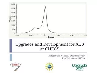
Upgrades and Development for XES at CHESS. Robert Cope, Colorado State University Ken Finkelstein, CHESS. Motivation and Goals Set for Summer. Want to improve XES capabilities and enhance user experience at beam line. Implementing multilayer mirrors in the monochromator

Upgrades and Development for XES at CHESS
E N D
Presentation Transcript
Upgrades and Development for XES at CHESS Robert Cope, Colorado State University Ken Finkelstein, CHESS
Motivation and Goals Set for Summer • Want to improve XES capabilities and enhance user experience at beam line. • Implementing multilayer mirrors in the monochromator • Goal: Model the multilayer mirrors and integrate into current simulations of beam line. • Goal: Automate calibration procedure, and produce easily usable calibration constants file. • Improve User experience • Goal: Add all necessary functionality to beam line data analysis tools. • Add to current calibration procedure: • Goal: Help implement secondary X-Ray source, reducing dependence on “precious synchrotron time.”
CHESS and X-Ray Emission Spectroscopy • XES works by looking at X-ray fluorescence coming from the source. Incident X-rays have enough energy to eject an inner shell electron, often a K-shell electron. The atoms fluoresce when an electron drops from a higher energy state down into the vacancy in a lower energy state. • Transition energies vary from element to element, thus XES is “element sensitive.” • XES is a good method of probing the electronic structure of atoms and crystals. • The C1 XES setup has been used to probe high energy electronic transitions, including K-α and K-β lines in samples such as iron. Right: Atom with Ligands. Source: Chris Pollock
X-rays and Emission Spectra We are interested specifically in the K-β lines, which are some of the highest energy emission lines. K-β lines result from an electron dropping from the M or N shells (principal numbers n = 3 and 4) down into the K shell (principal number n =1), and emitting X-rays. K-β Lines Source: Lawrence Berkeley National Laboratory X-ray Data Booklet
Improving XES efficiency. • Certain electronic transitions, such as the satellite K- β lines fluoresce very weaking compared to K-alpha. • Low flux silicon optics in the monochromator mean longer wait times to probe transitions. • We need a way to resolve transitions faster. • Solution: Multilayer Monochromator
Some Background: Beam Path Top Down View Analyzer Detector Sample/Detector Vortex Laue Xtal Analyzer I0 I1 Sample Incident Beam from CESR Side View Monochromator
Rowland Geometry R = 85cm QB (Mn Kb) ~ 84.3 deg QB (Mo Kb) ~ 81.1 deg Calculate detector & crystal vertical motion about H & H/2 center position using dE/E=DQB/tanQB-center . L = R sinQB P = R sin2QB H = R sin(2QB) detector Crystal bend radius = R P H P OD ~115mm R/2 L QB sample P Top view Side view Source: Ken Finkelstein
Detector Mechanism Left: The sample, analyzer crystals and the detector as they are setup at C1 Right: A picture of the spectrometer sitting inside the Helium chamber at C1 Source: Ken Finkelstein
Multilayer Optics In order to model the Multilayer mirror, we can treat each cell as a set of two classical optical layers. Modified Fresnel relations can then be used to determine reflectivity. We must account for multiple reflections in our theory. r = Er / E0 R = Ir / I0 Multilayer Mirror Incident X-Ray Reflections Air/Vacuum Θ Θ Top Layer Cell N Bottom Layer Cell N-1 Cell N-2 Cell 1 Substrate (R =0)
Modeling Multilayer Optics Need to model and simulate Multilayer optics so we know the angle to align the mirrors at, and how much reflectivity we will see for a given energy. Bmad is a library developed by David Sagan originally for charged particle simulation. It has been adapted for modeling synchrotron radiation. Bmad allows us to simulate the entire beam line, along with CESR to get a fuller prediction of what will happen when we change parameters and elements in the beam line. Bmad Logo Source: David Sagan
Modeling Multilayer Optics • Three models for Multilayer Optics: • Kinematic Approximation [1] • Parratt Recursion Formula [1],[3] • V.G. Kohn’s Analytic Formula [2] Advantages/Disadvantages: Kinematic: Very Simple/Rough approximation, fails in low-angle Parratt: Simple, Accurate/Long computation time Kohn: Accurate, Quick/Difficult to implement correctly
First Task: Accurately Implement Reflectivity Simulations Kinematic formula was not used because we need accurate data. Parratt and Kohn’s equations were coded into a Python script and evaluated, debugged and modified until results were produced that matched those provided by CXRO, and then used to check against Tao data. Simulations were tested with the proposed MLM, which is formed from multiple W/B4C bilayers, at many different angles and energies.
Simulating Multilayer Mirror Reflectivity Kohn’s Analytic Formula Parratt Recursion Formula Notice, Kohn’s analytic formula takes a order of magnitude less time to give results.
Simulating Multilayer Mirror Reflectivity Kohn’s Analytic Formula Parratt Recursion Formula
Implementing in Bmad My Simulations Bmad Simulations Kohn’s Analytic Formula is now implemented in BMAD, and matches my simulations Note: The Bmad x-axis is not angle, but instead the sin of the angle, which Corresponds to the normalized x-momentum, px = Px/P0, where P0 is the total Momentum, and Px is the x component of the total momentum.
Multilayer Optics Kohn’s multilayer formula is now implemented in Bmad. It matches the “golden standard,” Parratt’s recursion formula, and is an order of magnitude quicker. The next step will be to debug Laue geometry in Bmad, and begin simulating the proposed MLM setup in C1.
New Calibration Procedure • The drawback to using an MLM: Increase in flux proportional to increase in bandwidth. MLM has 100x more bandwidth, with ΔE/E = 1%. • Since the analyzer has a bandwidth roughly the same as the silicon optics, calibrating MLM energy to analyzer energy is difficult. • Solution: Use a Laue diffraction crystal in the beam path to resolve energy. The Laue crystal cuts a notch out of the incident beam given approximately by the Bragg relation: λ = 2d sin(Θ)
Laue Geometry in Diffracting Crystals Right: Artist’s rendition of beam profile after Laue diffraction. Laue Scattering When we talk about a crystal utilizing Laue geometry, diffraction planes are near normal to the surface for Laue geometry and near parallel to the surface for Bragg geometry. In both cases, the diffracted beam is emitted at an angle ~Θ, where Θ is the Bragg angle defined by λ = 2dsin(Θ). Also typically associated with Bragg scattering is the reflection of the incident waveform. A crystal in the Laue geometry produces scattering at the transmission interface, rather than reflection. Bragg Scattering Image Source: wikipedia.org
Calibration • As discussed in previous talk, calibration procedure has been coded into a SPEC script • SPEC is the X-ray data taking tool, which drives motors and reads detectors. • Calibration procedure generates a file containing analyzer and detector motor positions and corresponding Laue energies. • File is read in by my data analysis program or can be used later by beam line user in their own analysis
On to the Beamline • Now that we know how the reflectivity should look, and how to calibrate, how do we incorporate this at the beam line? Also how do we make it easier for users to make sure data is good? • Energy calibration from SPEC script (last presentation) is used in one of a couple of new PyMca modules for data analysis at the beam line. • New module fits Laue energy-analyzer position, and automatically changes spec scans in PyMca to energy space. Left: Workstation at C1 Beamline
More Data Analysis • Certain features such as error bars not stock on PyMca • Feature Implementation List: • Square Root of N Error Bars • Summing, Averaging, and Standard Deviation of Mean for selected curves • Scaling to Monitor Curve with error bar propagation • First and Second Derivatives of multiple curves • Normalization of curve integral to 1. • Most new features wrapped into convenient GUIs • Everything built on QT4 and Python, thus portable and free.
Completed Tasks: • Finished: • Calibration procedure for MLM ready, scripts written • Data analysis modules written, PyMca ready for Beam line • MLM reflectivity modeled with Parratt Forumla and Kohn’s Formula, integrated into Bmad • X-Ray tube ready to be physically mounted in Beam line for calibration without synchrotron: • To Be Completed: • Test simulations, scripts and modules with Synchrotron running • Get power supply for X-Ray tube, test with current setup. • Finish integrating Laue diffraction into Bmad
Acknowledgements: • Ken Finkelstein • David Sagan • Serena DeBeer • Armando Sole • Georg Hoffstaetter, Ivan Bazarov, Lora Hine, and Monica Wesley • CHESS staff • NSF
The End Questions?
Sources: • [1] – J. Als-Nielsen & D. McMorrow, “Elements of Modern X-Ray Physics”, 2001 • [2] – V.G. Kohn, “On the Theory of Reflectivity by an X-Ray Multilayer Mirror”, Phys. Stat. Sol. 187 • [3] – L. G. Parratt, “Surface Studies of Solids by Total Reflection of X-Rays”, Phys. Rev. 95, 359 (1954) • [4] - Ken Finkelstein, private communications. • [5] - Chris Pollock, Development of Kβ X-ray Emission Spectroscopy • [6] - Kazmirov et al., “Multilayer Optics at CHESS”
X-Ray Tube Adaptor Plate In order to use the calibration X-ray tube with the beam line, an adaptor for the current tube holder had to be designed to allow it to be inserted easily in to existing beam line clamps.
Assembled X-Ray Tube Holder The X-Ray tube holder adapter was machined and then fitted up to the enclosure. The fit is good, and the X-ray tube will be ready to be used on the beamline once a suitable power supply has been found.