Download
1 / 15
150 likes | 266 Vues
This document outlines key discussions from the September 2004 collaboration meeting concerning the START counter's function, specifically related to start signals for time-of-flight and beam pulse identification. Important design considerations include achieving minimal position and timing resolution, redundancy, and efficiency. The design involves an array of scintillator bars and fiber light guides optimized to operate in a low magnetic field. Future work will focus on optimizing the detector geometry and improving readout mechanisms while studying performance under varying conditions to ensure reliable kinematic reconstruction.

E N D
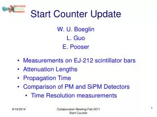
Start Counter W. BoeglinFIU Collaboration Meeting September 2004
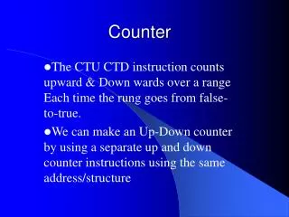
Questions in May What is the function of the START counter ? • Start signal for what : TOF, beam pulse identification ? • Vertex reconstruction: connect tracks to FDC’s , resolution (0.5 mm) ? • Part of the hardware trigger? • Part of the “software” trigger? • All of the above? • Readout/front-end electronics ADC/TDC logic Justification of requirements: physics driven • minimal position resolution requirements as a function z and direction • minimal timing resolution requirement • efficiency, redundancy, uniqueness • multiple scattering tolerance • alignment requirements, fiber location • phase space considerations, shadow regions (minimize impact of shadow regions) • kinematic reconstruction, over determination of tracks, redundancy
MC studies MC studies: need position resolution s ≤ 100 mm for a significant improvement of momentum resolution. Conference Call Minutes July 12. (thanks to Curtis Meyer, Ed Brash and David Lawrence) • focus first on start detector • study options for good position resolution for later design • upgrade detector if need arises later
Start Counter Design • array of scintillator bars (40) • fiber light guides to low field region (< 2kG) • read out by PMT: 5924-70 (Hamamatsu) • Segmentation: • 40 individual detectors • driven by back ground rate : 650 kHz for e+/e- with p > 1MeV ≈ 100kHz from g (latest GEANT) • 20 kHz background rate per scintillator
effective material thicknessfor trajectories at 90o : 5 mm 12cm
R&D Studies with H6614 System Eljen Technology EJ204 and EJ208 Scintillator bars: 70 x 3 x 0.5 cm
ADC spectra peak position as a functionof position in detector
time difference between 2detectors s of time difference as a function of position
Geometry of Detector • use 3p events • require at least 1 hit in detector • minimize length of detector
l = 50 cm, zd = -2.5 l = 55 cm , zd = 0. l = 55 cm , zd = 1.5 l = 60 cm , zd = 2.5
l = 50 cm, zd = -2.5, etot = .955 l = 55 cm , zd = 0., etot = .991 l = 55 cm , zd = 1.5, etot = .991 l = 60 cm , zd = 2.5, etot = .995
zv distributions, l = 60 cm, zd = 2.5 cm min 1 hit 3 hits 2 hits 1 hit
Readout • H6614-70 system (Hamamatsu): • gain 107 • photo cathode well matched to EJ200, 208 scintillator • according to data sheet, practically no gain loss up to 2kG • expensive ≈ $2000-$2500 Single ended readout: time variation due to light propagation 3 - 4ns • double ended readout with mean timer preferred • need transport light from front end of scintillator • possible with fibers (some material is added)
Future work to be performed • further optimize number of scintillators and geometry • study performance of PMT in magnetic field • design and proto type light guides & connectors • is front end readout possible ? • mean timers • design support structure for scintillators