Download

1 / 33
530 likes | 1.13k Vues
Structural scales and types of analysis in composite materials. Daniel & Ishai: Engineering Mechanics of Composite Materials.

E N D
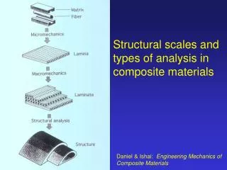
Structural scales and types of analysis in composite materials Daniel & Ishai: Engineering Mechanics of Composite Materials
Micromechanics- which fibre?- how much fibre?- arrangement of fibres? >>> LAYER PROPERTIES (strength, stiffness) • Laminate Theory- which layers?- how many layers?- how thick? >>> LAMINATE PROPERTIES • LAMINATE PROPERTIES >>> BEHAVIOUR UNDER LOADS (strains, stresses, curvature, failure mode…)
Polymer composites are usually laminated from several individual layers of material. Layers can be ‘different’ in the sense of: • different type of reinforcement • different geometrical arrangement • different orientation of reinforcement • different amount of reinforcement • different matrix
Typical laminate configurations for storage tanks to BS4994 Eckold (1994)
fibre direction E2 E1 The unidirectional ply (or lamina) has maximum stiffness anisotropy - E1»E2
90o 0o We could remove the in-plane anisotropy by constructing a ‘cross-ply’ laminate, with UD plies oriented at 0 and 90o. Now E1 = E2.
But under the action of an in-plane load, the strain in the relatively stiff 0o layer is less than that in the 90o layer.Direct stress thus results in bending:
This is analogous to a metal laminate consisting of one sheet of steel (modulus ~ 210 GPa) bonded to one of aluminium (modulus ~ 70 GPa): P Powell: Engineering with Fibre-Polymer Laminates Note the small anticlastic bending due to the different Poisson’s ratio of steel and aluminium.
In this laminate, direct stress and bending are said to be coupled. Thermal and moisture effects also result in coupling in certain laminates - consider the familiar bi-metallic strip:
A single ‘angle-ply’ UD lamina (ie fibre orientation q 0o or 90o) will shear under direct stress: q
In a 2-ply laminate (q, -q), the shear deformations cancel out, but result in tension-twist coupling:
To avoid coupling effects, the cross-ply laminate must be symmetric - each ply must be mirrored (in terms of thickness and orientation) about the centre.Possible symmetric arrangements would be: 0o 90o 90/0/0/90 [90,0]s 0/90/90/0 [0,90]s
Both these laminates have the same in-plane stiffness. How do the flexuralstiffnesses compare? 0o 90o 90/0/0/90 [90,0]s 0/90/90/0 [0,90]s
The two laminates [0,90]s and [90,0]s have the same in-plane stiffness, but different flexural stiffnesses • Ply orientations determine in-plane properties. • Stacking sequence determines flexural properties. • The [0,90]s laminate becomes [90,0]s if rotated. So this cross-ply laminate has flexural properties which depend on how the load is applied!
VAWT (1987) HAWT (2004)
To avoid all coupling effects, a laminate containing an angle ply must be balanced as well as symmetric - for every ply at angle q, the laminate must contain another at -q. • Balance and symmetry are not the same:0/30/-30/30/0 - symmetric but not balanced = direct stress/shear strain coupling.30/30/-30/-30 - balanced but not symmetric = direct stress/twist coupling.
The [0,90] cross-ply laminate (WR) has equal properties at 0o and 90o, but is not isotropic in plane. • A ‘quasi-isotropic’ laminate must contain at least 3 different equally-spaced orientations: 0,60,-60;0,90,+45,-45; etc. ODE/BMT: FRP Design Guide
UD (0o) laminate proportion of plies at 90o proportion of plies at 0o proportion of plies at 45o UD (90o) laminate Carpet plot for tensile modulus of glass/epoxy laminate
0/90 (cross-ply)E = 29 GPa 0/90/±45 (quasi-isotropic)E = 22 GPa
Classical Plate Analysis • Plane stress (through-thickness and interlaminar shear ignored). • ‘Thin’ laminates; ‘small’ out-of plane deflections • Plate loading described by equivalent force and moment resultants. • If stress is constant through thickness h, Nx = h sx, etc.
Classical Plate Analysis • Plate bending is described by curvatures kx, ky, kxy. • The ‘curvature’ is equal to 1 / radius of curvature. • Total plate strain results from in-plane loads and curvature according to: where z is distance from centre of plate
Classical Plate Analysis Stress = stiffness x strain: Giving:
In simpler terms: [A] is a matrix defining the in-plate stiffness. For an isotropic sheet, it is equal to the reduced stiffness multiplied by thickness (units force/distance). [B] is a coupling matrix, which relates curvature to in-plane forces. For an isotropic sheet, it is identically zero. [D] is the bending stiffness matrix. For a single isotropic sheet, [D] = [Q] h3/12, so that D11=Eh3/12(1-n2), etc.
Classical Laminate Analysis • Combines the principles of thin plate theory with those of stress transformation. • Mathematically, integration is performed over a single layer and summed over all the layers in the laminate.
Classical Laminate Analysis • The result is a so-called constitutive equation, which describes the relationship between the applied loads and laminate deformations. [A], [B] and [D] are all 3x3 matrices.
Classical Laminate Analysis • Matrix inversion gives strains resulting from applied loads:where:
Effective Elastic Properties of the Laminate (thickness h) Bending stiffness from the inverted D matrix:
Classical Laminate Analysis - assumptions 1 Layers in the laminate are perfectly bonded to each other – strain is continuous at the interface between plies. 2 The laminate is thin, and is in a state of plane stress. This means that there can be no interlaminar shear or through-thickness stresses (tyz = tzx = sz = 0). 3 Each ply of the laminate is assumed to be homogeneous, with orthotropic properties. 4 Displacements are small compared to the thickness of the laminate. 5 The constituent materials have linear elastic properties. 6 The strain associated with bending is proportional to the distance from the neutral axis.
Steps in Classical Laminate Analysis 1. Define the laminate – number of layers, thickness, elastic and strength properties and orientation of each layer. 2. Define the applied loads – any combination of force and moment resultants. 3. Calculate terms in the constitutive equation matrices [A], [B] and [D]. 4. Invert the property matrices – [a] = [A]-1, etc. 5. Calculate effective engineering properties. 6. Calculate mid-plane strains and curvatures. 7. Calculate strains in each layer. 8. Calculate stresses in each layer from strains, moments and elastic properties. 9. Evaluate stresses and/or strains against failure criteria.
Use of LAP software to calculate effect of cooling from cure temperature (non-symmetric laminate).