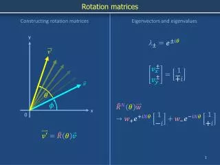
Polarization Jones vector & matrices
Polarization Jones vector & matrices. Phys 375. Matrix treatment of polarization. Consider a light ray with an instantaneous E-vector as shown. y. E y. x. E x. Matrix treatment of polarization. Combining the components


Polarization Jones vector & matrices
E N D
Presentation Transcript
PolarizationJones vector & matrices Phys 375
Matrix treatment of polarization • Consider a light ray with an instantaneous E-vector as shown y Ey x Ex
Matrix treatment of polarization • Combining the components • The terms in brackets represents the complex amplitude of the plane wave
Jones Vectors • The state of polarization of light is determined by • the relative amplitudes (Eox, Eoy) and, • the relative phases ( = y - x) of these components • The complex amplitude is written as a two-element matrix, the Jones vector
y x Jones vector: Horizontally polarized light The arrows indicate the sense of movement as the beam approaches you • The electric field oscillations are only along the x-axis • The Jones vector is then written, where we have set the phase x = 0, for convenience The normalized form is
y x Jones vector: Vertically polarized light • The electric field oscillations are only along the y-axis • The Jones vector is then written, • Where we have set the phase y = 0, for convenience The normalized form is
y x Jones vector: Linearly polarized light at an arbitrary angle • If the phases are such that = m for m = 0, 1, 2, 3, … • Then we must have, and the Jones vector is simply a line inclined at an angle = tan-1(Eoy/Eox) since we can write
y x Circular polarization • Suppose Eox = Eoy = A and Ex leads Ey by 90o=/2 • At the instant Ex reaches its maximum displacement (+A), Ey is zero • A fourth of a period later, Ex is zero and Ey=+A t=0, Ey = 0, Ex = +A t=T/8, Ey = +Asin 45o, Ex = Acos45o t=T/4, Ey = +A, Ex = 0
Circular polarization • The Jones vector for this case – where Ex leads Ey is • The normalized form is, • This vector represents circularly polarized light, where E rotates counterclockwise, viewed head-on • This mode is called left-circularly polarized light • What is the corresponding vector for right-circularly polarized light? Replace /2 with -/2 to get
Elliptically polarized light • If Eox Eoy, e.g. if Eox=A and Eoy= B • The Jones vector can be written counterclockwise clockwise Here A>B
Jones vector and polarization • In general, the Jones vector for the arbitrary case is an ellipse ( m; (m+1/2)) y Eoy b a x Eox
y x Optical elements: Linear polarizer • Selectively removes all or most of the E-vibrations except in a given direction TA Linear polarizer
Jones matrix for a linear polarizer Consider a linear polarizer with transmission axis along the vertical (y). Let a 2X2 matrix represent the polarizer operating on vertically polarized light. The transmitted light must also be vertically polarized. Thus, Operating on horizontally polarized light, Linear polarizer with TA vertical. Thus,
Jones matrix for a linear polarizer • For a linear polarizer with a transmission axis at
y x Optical elements: Phase retarder • Introduces a phase difference (Δ) between orthogonal components • The fast axis(FA) and slow axis (SA) are shown FA SA Retardation plate
Jones matrix of a phase retarder • We wish to find a matrix which will transform the elements as follows: • It is easy to show by inspection that, • Here x and y represent the advance in phase of the components
Jones matrix of a Quarter Wave Plate • Consider a quarter wave plate for which |Δ| = /2 • For y - x = /2 (Slow axis vertical) • Let x = -/4 and y = /4 • The matrix representing a Quarter wave plate, with its slow axis vertical is,
Jones matrices: Half-wave Plate • For |Δ| = HWP, SA vertical HWP, SA horizontal
Optical elements: Quarter/Half wave plate • When the net phase difference Δ = /2 : Quarter-wave plate Δ = : Half-wave plate /2
y x Optical elements: Rotator • Rotates the direction of linearly polarized light by a particular angle SA Rotator
Jones matrix for a rotator • An E-vector oscillating linearly at is rotated by an angle • Thus, the light must be converted to one that oscillates linearly at ( + ) • One then finds