State Transition Diagrams Chapter 13
160 likes | 371 Vues
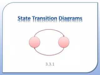
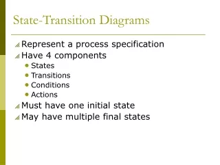
State Transition Diagrams Chapter 13. Another “ tool ” for depicting the Design An integral part of the De S CRIP T R State Transition. State Transition Diagram. A state transition diagram is a technique to depict: The states of an entity The transitions of states of the entity

State Transition Diagrams Chapter 13
E N D
Presentation Transcript
State Transition DiagramsChapter 13 • Another “tool” for depicting the Design • An integral part of the DeSCRIPTR • State • Transition
State Transition Diagram • A state transition diagram is a technique to depict: • The states of an entity • The transitions of states of the entity • The trigger or the event that caused the transition of state of the entity • The entity may be a physical device such as a light switch or a vending machine; it may be a softwaresystem or componentsuch as a word processor or an operating system; it may be a biological system such as a cell or a human; or - - - - This modeling technique came from a more formal area called automata theory. State transition diagram depicted a Finite State Machine.
Software Program View • The end product of a software is a program which executes. In depicting the program (or an object) we can consider: • Variableswhich take on different values • Control structure and assignment statements(events) in the program that change the values of the variables; but “little” is said about how the control structure or the statements work • Combination of values of the data (variables & constants) at any point of • the program represent the programstate at that point. • 2. The change made to the values of the variables through assignment statements • represent a transition of state
A very simple example light switch (page 368 of your text) From State (light) To State (light) Alt Event (switch) switch light on turnOff off [l_st=on] TurnOff ( ) off turnOn on [l_st=off] TurnOn ( ) 2. “State transition table” for light with switch events 1. “Sequence diagram” (alternative fragment) forswitch and light interaction turnOff light on light off turnOn 3. “State transition diagram” for light with switch events
A little “more” on the light switch turnOff turnOff turnOff on off on off turnOn turnOn turnOn What happens if we turn on a light that is already on? state can “transition” to its current state
Using State Transition Diagram • Model the entity at the “abstraction” level where the number of states is“manageable.” • List (design) the states (should not be large) • List eventsthat will trigger the state transition (should not be big) • There must be a starting state • There must be a terminating state or states • Design the transition rules(the bulk of your design work is thinking through the transition rules) 1.The above is not necessarily performed in sequence; iterate through these. 2. Even with a modest number of states and events, the state transition diagram, which really depicts the transition rules, can be enormous.
Designing the Voice Recorder(similar to example on page 397 of text) • For the entity, voice recorder, design the states of this entity: • How many states does ( somewhat based on requirement) a voice recorder have? • Set of recorder states = { off, on, play, record, erase, stop, error-msg } • What are the initial and terminating states? • Initial state = {off} • Terminating state = {off} • List the events that will change the state of the entity: • What are the events that will change the recorder’s states? • “Input signals” = { 1, 2, 3, 4, 5, 6 } which corresponds to: { push off, push on, push play, push record, push erase, push stop} Note: no “rewind” state
Designing the Voice Recorder(example form page 397 of text) – cont. • Design the transition rules for the voice recorder from state events to state off 2 on off 1 off on 1 off More transition rules: 1. Any state transition not described here will transition to error-msg state 2. once in error-msg state, the system “displays a message” and automatically transitions to stop state. on 3 play on 4 record on 5 erase play 6 stop record 6 stop erase 6 stop stop 3 play stop 4 record stop 5 erase stop 1 off • Events: {1=push off, 2=push on, 3=push play, 4=push record, 5=push erase, 6=push stop}
State Transition Diagram ofVoice Recorder • Events: {1=push off, 2=push on, 3=push play, 4=push record, 5=push erase, 6=push stop} 1 1 stop On Off [always true] 1 2 3 Error-msg 4 3 5 5 4 6 play 6 6 erase record Couple things to note: 1. All non-specified events for all the states go to “Error-msg” state - - - is that o.k? 2. What happens when a signal of 6 comes in when in state “ON” - - - error message? 3. How do you specify “display error message” in Error-msg state ? 4. How do you specify “Starting” and “Terminating” state ?
UML’s “Improvements” on State Transition Diagrams • Event may be expressed with a string: event-signature [guard] / action-expression • State symbol may contain several compartments: • Name • Processing activities in the form of : • Action-label / Action-expressions • Action-labels: • Entry – specifies activities upon state entry • Exit – specifies activities upon state exit • Do – specifies activities to be performed after entry but before exit • Include – names another state diagram to be used for “nested” state transition diagram for further refinement • Action-expression specifies the activities to be performed. • Instead of include, there may be a “stubbed” state which can be expanded later. • The state diagram may contain another state diagram (nested diagram) in its compartment
UML State Transition Composite Diagram Example(cruise control system - similar to page 401 of text) off onBtnclick offBtnclick On Note: 1.the start and terminating states 2. When entering a composite diagram, the start state must be clearly defined. 3. How we exit this composite diagram from the freeSpeed state and actually enter “off” state pedalSpeed entry / spLock:= undefined engage pressBreak setSpeed freeSpeed entry/ spLock := current speed do / lockState := on entry / spLock := undefined do / lockState:= off exit / set offBtnclick
Some Deeper (Advanced) UML State Diagrams • Concurrent Composite State Diagram contains two or more composite state diagrams that may be executed in parallel; state diagram is divided up into compartments by parallel dotted lines. Concurrent Composite State StateW Event-K StateZ Note: 1. Transition to a concurrent composite state boundary will enter initial states of all the concurrent state diagrams 2. Or one can specify the sub states which will be entered, along with the one specified start state 3. similarly exits can be specified Event-A
More Advanced UML State Transition Diagramwith Synchronization Mechanism EW= east-west NS=north-south SignalOperationState after 40 sec after 5 sec EW Green EW Yellow EW Red after 35 sec after 45 sec NS Red after 30 sec NS Green NS Yellow after 5 sec Synch signal used to help regulate transition SynchronizedSignalOperation after 35 sec EW Red Synch signal used to help regulate transition after 40 sec after 5 sec EW Green EW Yellow 1 1 after 45 sec NS Red after 5 sec after 30 sec NS Yellow NS Green
Transition Junction & Compound Transition near_by store [cold=yes] at_home shopping_urge [cold=no] far_away mall [cold=extreme] on-line shopping
Advanced Mechanism to set History RadioOn The history of preset state is “remembered” if the radio is turned on after it is turned off History state, H,says re-enter the state that was last active setFM Preset FM station setAM Preset AM station setCD Preset cd music off turnOn H turnoff
Read at least one example from the text on your own.(Especially the Dialog Map and UI diagram)