Download
1 / 22
220 likes | 348 Vues
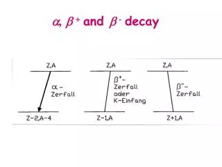
Target chase, decay and absorber cooling for LBNE. A. Marchionni , Fermilab 8th International Workshop on Neutrino Beams & Instrumentation CERN, November 2012. High beam-induced heat loads! LBNE cooling for target chase and decay pipe base design 700 kW: air cooling only

E N D
Target chase, decay and absorber cooling for LBNE A. Marchionni, Fermilab 8th International Workshop on Neutrino Beams & Instrumentation CERN, November 2012 • High beam-induced heat loads! • LBNE cooling for target chase and decay pipe • base design • 700 kW: air cooling only • 2.3 MW: add water cooling panels in target chase • LBNE cooling for absorber • Final considerations
Target pile and decay pipe cooling • The base design is to have • air cooled decay pipe, with air flowing at high velocity in the annular gap of two concentric decay pipes • air cooled target pile at 700 kW and a combination of air cooling and water cooling at 2.3 MW • common air supply for target pile and decay pipe at 15 °C. • The reference design has an airflow rate of 50,000 scfmfor the decay pipe • The NuMI target pile has an airflow rate of 25,000 scfm at 700 kW • Scaling from the 46” NuMI chase width to the 54” LBNE chase width, increases the LBNE target pile airflow rate to 35,000 scfm for 700 kW • for 700 kW, the 35,000 scfm airflow removes the energy deposited by the beam in the bulk steel shielding • for 2.3 MW, water cooling removes about 80% of the deposited energy and the balance is removed by the 35,000 scfmairflow
Decay Pipe Design Waterproof barrier all around. Decay pipe air return Drainage layer all around. 5.5 m concrete Decay Pipe Decay pipe air supply flows in the 20 cm annular gap Waterproof barrier all around. • Inner pipe: ½” thick, corrosion-protected mild carbon steel, supported on outer pipe with radial supports, 4 m inside diameter. • Outer pipe: ½” thick, corrosion-protected mild carbon steel, embedded in shielding concrete, 4.4254 m inside diameter. • Annular airflow gap between the concentric pipes is 20 cm. Soil all around.
Decay Pipe Cooling • The inner ½” thick steel pipe absorbs 56% of the energy before it can reach the concrete, and the annular air gap prevents that heat from being conducted out to the concrete • Peak heating is 35 m from upstream end of decay pipe • Closed air loop, 50,000 scfm flow rate, high velocity heat transfer coefficient 21 W/m2K • Air supply temperature = 15 °C (59 °F) • Air exit temperature from decay pipe = 33 °C (91.4 °F) • All operating temperatures are a concern but geomembrane temperature is a major concern • Geomembraneservice life is a function of temperature. • Detailed information only available for HDPE • Geomembrane“strength half-life” from Rowe (2005) • 130 yrs @ 35o C • 80 yrs @ 40o C • 35 yrs @ 50o C
Decay Pipe Cooling Analysis Temperatures at point of peak heating • Concrete peak temperature 40.5 °C • Geomembrane temperature ≤ 35 °C
6” marble layer Target hall floor 6” borated polyethylene cover Carriage lateral beam (typ) 18” shielding steel * Fixed chase shielding Concrete * T-blocks T-blocks T-blocks * T-blocks T-blocks T-blocks * * * Steel Concrete Chase Horn 1 Horn 2 Target/baffle carrier Cooling panels Chase Steel Steel Concrete Concrete
Target Hall Shield Pile Design Carriage lateral beam Marble layer Carriage longitudinal beam Chase Cooling panel Horn 1 2” thick Chase Chase cooling panels Steel Concrete 4” thick
Target Hall cooling panels Radiation labyrinth step Gun-drilled cooling channel In the base design cooling panels are made of carbon steel
Target Hall Shield Pile “Air Block” • NuMI target pile air block sheet. It is placed between bulk shielding layers. • LBNE target pile air block sheet:
FEM 3-D Thermal Analysis of NuMI @ 700 kW 25,000 scfm air flow • A 3D thermal finite element model has been developed for NuMI target hall shielding blocks. • For the 700 kW ME configuration, the maximum static temperature is 153C on the chase side wall (“blue-block”), and it is towards the downstream end of Horn 1. • The radiation heat to horn and water tank is 4,290 watts. After all active cooling and heat are shut off, the horn temperature will not exceed 100 C.
LBNE Target Hall Shield Pile Cooling Estimated operating temperature for 700 kW beam is 170 °C with air cooling and no chase panel water cooling. Panel heat load is 2.4 W/kg. For comparison: Estimated operating temperature for 2.3 MW beam is 75 °C with air cooling plus chase panel water cooling. Panel heat load is 8 W/kg. 35000 scfm Chase height = 63"
Absorber design Al core blocks (60”x60”x12”) Iron core blocks (60’x60”x12”) Al pre-mask Iron shielding blocks Concrete Absorber-core blocks will be instrumented with at least eight thermocouples, distributed radially every 45at a radius of approximately 400 mm
Absorber cooling At least three continuous Al water-cooling lines are welded to the four sides of the core blocks Water temperature 25 °C Iron Aluminum
Absorber temperature analysis Longitudinal energy deposition in the Al core, normal operation Steady state temperature for the 3rd Al core block, normal operation Accident condition, 15 direct beam pulses superimposed to steady conditions
Final considerations • Base design for cooling of target chase, decay pipe and absorber has been presented, still at the conceptual phase • radiological issues have been taken into account • Experience with NuMI shows that tritium release and NOx induced corrosion can be minimized by dehumidification of air • Still, need to consider the alternative of a He filled decay pipe (water cooled?) • increase in ν flux by 5-10% • presence of air limited to target chase, no transport of target chase air in decay pipe region • Utilization of carbon steel for water cooling needs careful consideration • many thanks for sharing T2K experience
Target Hall Shield Pile Air Flow • Cross section through horn 1 at beam sheet point MC-ZERO. • Steel shielding is cross-hatched. • Top supply airflow. Flows downstream to upstream. Flows through T-blocks and other shielding blocks into the chase. • “Air block” sheet metal separates the supply and return airflows. • Side and bottom supply airflows. Flows downstream to upstream. • Some air flows through the gaps in the bulk shielding. • Chase return airflow. 7” wide side passage 5” high bottom passage
Neutrino Beam Decay Pipe 2’- 0” [0.6M] (MINIMUM COVER) VARIES WITH DEPTH OF DECAY PIPE 5 1 51’-6” [15.7 M] CONCENTRIC ½” THICK STEEL PIPES. DECAY PIPE / INNER PIPE: 4M DIAMETER. OUTER PIPE: 4.4 M DIAMETER. 8” [203 mm] ANNULAR GAP FOR AIRFLOW BETWEEN THE INNER AND OUTER PIPES. 50’-6” [15.4 M] 50’-6” [15.4 M] 18’ [5.5 M] MINIMUM CONCRETE SHIELDING 54’-3” [16.5 M] 30° RADIAL SPACING FOR ½” THICK STEEL PLATE DISCONTINUOUS LONGITUDINAL WEBS. EACH WEB IS 5” LONG. WEB LONGITUDINAL SPACING IS 6”.
Absorber Complex – Longitudinal Section The Absorber is conceptually designed for 2.3 MW A specially designed pile of aluminum, steel and concrete blocks, some of them water cooled which must contain the energy of the particles that exit the Decay Pipe. Decay Pipe 94’ Below Grade Beamline Decay Pipe ~ 16’ into rock