Verilog
Verilog. Digital Computer Logic Kashif Bashir WWW: http//:www.kashifpaf.greatnow.com Email: kashif@pafkiet.edu.pk. Module Outline. What is Verilog? Verilog modules Types of Verilog Code Verilog simulators Example Verilog Code


Verilog
E N D
Presentation Transcript
Verilog Digital Computer Logic Kashif Bashir WWW: http//:www.kashifpaf.greatnow.com Email: kashif@pafkiet.edu.pk
Module Outline • What is Verilog? • Verilog modules • Types of Verilog Code • Verilog simulators • Example Verilog Code • Working with Silos
Verilog Basics • Verilog is a HDL – Hardware Description Language • Originated at Gateway Design Automation around 1987, later purchased by Cadence Design Systems • The other HDL is VHDL (VHSIC-HDL) • Originally Verilog only meant to simulate • Later on, synthesis also added • A subset of Verilog that can be synthesized is called RTL Verilog
Verilog Modules • A basic entity is called a module in Verilog • Modules have input ports and output ports • You can instantiate modules inside other modules • You have to write a test-bench module to test your design modules • The test-bench module instantiates your design modules, gives them appropriate set of inputs and lets you observe the outputs of interest
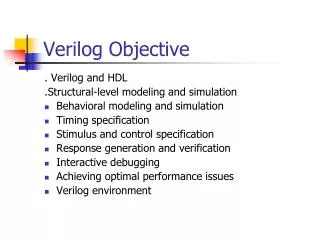
Types of Verilog Coding • Behavioral – just like a normal programming language but with the difference of time • Structural – uses primitives for basic gates, etc. and connects devices much in the same way that you would on a breadboard • RTL Verilog – a subset of Verilog that can be synthesized. Synthesis means automatic generation of the digital circuit based on the Verilog code. Synthesis is done using a synthesis tool
Verilog Simulators • There are many available such as from: • Synopsys - VCS • ModelTech – Modelsim • Silos • Many others • We shall use Silos
Example – SR Latch // This is a comment // A circuit to implement a SR Latch // module srlatch(s, r, q, qbar); input s, r; output q, qbar; reg q, qbar; wire s, r; always @ (s or r) begin q = ~(r | qbar); qbar = ~(s | q); end endmodule
A Test Bench for SR Latch // Testbench for the SR latch // module tbsrlatch(); wire q, qbar; reg s, r; srlatch mysrlatch(s, r, q, qbar); initial begin s = 1'b0; r = 1'b0; #10 s = 1'b1; r = 1'b0; #10 s = 1'b0; r = 1'b0; #10 s = 1'b0; r = 1'b1; #10 s = 1'b0; r = 1'b0; #10 s = 1'b1; r = 1'b1; #10 s = 1'b0; r = 1'b0; #10 s = 1'b0; r = 1'b1; #50; $finish; end endmodule
Working with Silos • A Windows-based Verilog Compiler and Simulator • Comes with a GUI and waveform display • Download at http://www.simucad.com • Demo version password is sim2001 • You need to be connected to Internet to install it • You create a project first and then add Verilog code files to it
Another Example // Verilog code for Problem 4-9 // module posedgedflipflop(d, clock, q, qbar); input d, clock; output q, qbar; wire q, qbar; wire d, clock; nand n1(outn1, outn4, s); nand n2(s, outn1, clock); nand n3(r, s, clock, outn4); nand n4(outn4, r, d); nand n5(q, s, qbar); nand n6(qbar, r, q); endmodule
Test Bench Another Example // Testbench for the Positive Edge- // Triggered D Flip-flop // module tbposedgedflipflop(); wire q, qbar; reg d, clock; posedgedflipflop myposedgedflipflop(d, clock, q, qbar); initial begin d = 1'b0; clock = 0; #10 d = 1'b0; clock = 1; #10 d = 1'b1; clock = 0;
Test Bench Another Example - Continued #10 d = 1'b1; clock = 1; #10d = 1'b1; clock = 0; #10 d = 1'b0; clock = 1; #10d = 1'b0; clock = 0; #10 d = 1'b0; clock = 1; #10d = 1'b1; clock = 0; #10 d = 1'b1; clock = 1; #10d = 1'b0; clock = 0; #10d = 1'b0; clock = 1; #50; $finish; end endmodule