RPC Electronics
RPC Electronics. Overall system diagram At detector Inside racks Current status Discriminator board TDC board Remaining task. On chamber. TDC. Disc. 16 channels cable input. Altera Cyclone II FPGA. 32 channel. 16 channels cable input. Serial download. 20X4rows connectors.


RPC Electronics
E N D
Presentation Transcript
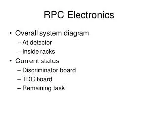
RPC Electronics • Overall system diagram • At detector • Inside racks • Current status • Discriminator board • TDC board • Remaining task
On chamber TDC Disc. 16 channels cable input Altera Cyclone II FPGA 32 channel 16 channels cable input Serial download 20X4rows connectors 32 bits L1 trigger (Timing bin = 106ns/64) Data Disc. 16 channels cable input Altera Cyclone II FPGA 32 channel 16 channels cable input Serial download RPC(HBD) crate/BUS structure 6Ux160 mm VME size Output To DCM T D C T D C Output To L1 Clock fanout Clock Master 8/6 TDCs Slow Control GTM DCM L1 primitives L1
RPC Discriminator board CMS RPC discriminator chip Temporary programming jig power LVDS discriminator output Signal flow RPC TDC board L1 data DCM data Cable adapter board
Signal Cable Half octant Module edge 3M (Gray) 3432-5302 RPC TDC 64 ch RPC disc 32 ch 3M (Gray) 3417-6640 Adapter Board 16 short RG174 cables 2-3 m cable ? 8 meters cable ? 3M N3432-L302RB 3M 6834-4500PL Or 8534-4500pl 3M 4640-7300 3M (gray) 3431-5302 2-3 m cable? 8 meter cable ? Adapter Board 3M (Black) D89140-???? 3M (Black) 3432-5302RB Signal Cable : 40 conductors twist flat ribbon cable 3M 1700/40 Twisted Pair, Flat Cable, .050" 28 AWG Stranded Fire rating VW-1
RPC discriminator power Molex 43650-0412 4 circuits 94-V0 Molex 43645-0400 UL94 V0 Molex 43030-0008 20-24 gauge wire Max. current 5A. fuse Discriminator RPC board internally has +5 Analog, +5 Digital, +3V Digital through low drop regulators Power connector need +6V analog, +6V digital The board draws 0.42A total current (analog+digital) The current thinking is we will combine analog and digital power at the patch panel connector at RPC half octant edge.
LV supplies wires Chamber end Inside the chamber module Half octant Module edge Power Connector ~1.5cm Panel Thickness: 1.60mm (.063") max. Molex 39012105 Molex 0015060106 4.20mm (.165") Pitch Mini-Fit Jr.™ Receptacle 5557 series Dual Row 4.20mm (.165") Pitch Mini-Fit BMI™ Plug 42475 series Dual Row With Panel Mount Ears 0015-06-0146 14 position (94V-0) 39012145 – 14 position (94V-0) Molex 46083-3212 16 gauge wires, 9A max 100 cycles mating 12 connectors for RPC3 Molex 46134-3212 16 gauge wires, 9A max 100 cycles mating
FEM crate ERNI 114402 2mm HM standard 9(8)A at 200c per contact 94V-0 VME 6U mechanical form factor All modules has fuse TDC 0.6A when power up ~1A at full speed 4V (3.3V and 1.2 internally) Clock fanout module ~.8A Xmit module ~.4A after power up, <1A a full speed L1 trigger output module design in progress Clock Master 0.9V at 5.5V (one per rack) 1.1A at 4V
HBD crate power connection (back view) with Bus Bar Analog GND -3.5V +4V -3.5V Clock fanout cable Meritec 980319-024(-048) UL 94V-0 Bus Bar 5V(4V) Digital GND
High Voltage Power supply • We use CAEN SY1527LC crate supply • 8 U size • RPC1N and 1S probably can just share one power supply
DC power distribution • After half octant module, all discriminator board power(2 wires per module) should be wire to rack. • 16*6 RPC discriminator for station 3 • DC power fanout at din rail mounted fuse block at the FEM rack (~1A fuse) • Do not share power supply between station. • Use Low noise converter pack (QPAC) • For the FEM crate power • do not share power between crates.
Channel count etc… (one side) The crate size is like 6U VME crate. I would like to limit the length discriminator cable to 10 meters. (to be tested about jitters) The RPC2, 3, we will need to find the crate space near the detector. Crate need to be recess in the rack. Cable routing space needed in front of the crate.