Download
1 / 49
530 likes | 856 Vues
Lecture 5 Viewing and projections. Viewing In OpenGL The camera frame Other view APIs Projections Perspective projections Parallel projections View volumes Parallelpiped Frustum. Viewing. Modeling coords What we model object in Independent of viewing

E N D
Lecture 5Viewing and projections • Viewing • In OpenGL • The camera frame • Other view APIs • Projections • Perspective projections • Parallel projections • View volumes • Parallelpiped • Frustum
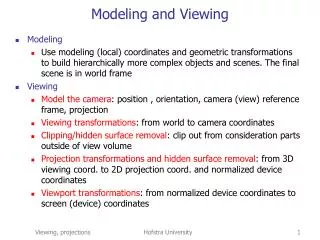
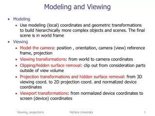
Viewing • Modeling coords • What we model object in • Independent of viewing • OpenGL uses the modeling part of the model-view matrix to convert from the modeling frame to the world frame • OpenGL camera • Placed at origin of world frame pointing in negative z direction
Viewing • If we model scene around origin the camera will not see all objects so we must 1) move camera back, or 2) move scene to in front of camera • Sequence of operations 1.Begin with model_view matrix = identity matrix 2.Define objects using glVertex 3.Apply model_view matrix to move world frame to camera frame (I.e. move objects to eye space) • *If we now position an object, is w.r.t. the repositioned world frame These are equivalent operations
Camera positioning • OpenGL Example • This moves points Or we can think of it as world space positioning the camera glMatrixMode (GL_MODEL_VIEW); glLoadIdentity (); glTranslate (0, 0, -d); glRotate (0, -90, 1, 0); z=-d -90deg z=+d 90deg M = TR = T(0,0,-d) Ry(-90) M-1 = R-1T-1 = Ry(90) T(0,0,d)
y (1,sqrt(2)) d 1 z sqrt(2) Example:Find isometric view (p205) y 45deg (1,1,1) (-1,1,1) z y (0,1,sqrt(2)) d = sqrt(1*1+sqrt(2)*sqrt(2)) = sqrt(1+2) = sqrt(3) cos = sqrt(2)/sqrt(3) = sqrt(6)/3 sin = sqrt(1)/sqrt(3) = sqrt(3)/3 = acos(sqrt(6)/3) = 35.26 z y z R = RxRy= sqrt(2)/2 0 sqrt(2)/2 0 0 1 0 0 -sqrt(2)/2 0 sqrt(2)/2 0 0 0 0 1 1 0 0 0 0 sqrt(6)/3 sqrt(3)/3 0 0 -sqrt(3)/3 sqrt(6)/3 0 0 0 0 1
Defining a camera frame 1. Position camera (VRP) set_view_reference_point (x, y, z) 2. Specify view plane by its normal (VPN) set_view_plane_normal (nx, ny, nz) 3. Specify camera up vector (VUP) set_view_up (vupx, vupy, vupz) (VUP must be orthogonal to VPN, so project to VP) 4. This gives us two orthogonal vectors, v and n find the third, u = v x n n vup v VP vrp u
Creating a camera frame • Given: p, n (unit), and up • Find: view matrix, V, which takes x,y,z to u,v,n • x,y,z are world coords, u,v,n are eye coords • V= RT = ux uy uz 0 vx vy vz 0 nx ny nz 0 0 0 0 1 1 0 0 -vrpx 0 1 0 -vrpy 0 0 1 -vrpz 0 0 0 1 pu pv pn 1 px py pz 1 = V Need to find u and v
Creating a camera frame • Find v: • Find u: 1. Project up onto n ([(up*n)/(n*n)]n) 2. Subtract the result (the comp. of up in the direction of n) from up to get v, which is orthogonal to n and thus lies in the plane VP: v = up - [(up*n)/(n*n)]n v = (I - nnT/nTn) up 3. Normalize up v u VP n This is the projection onto VP. What does this remind you of? 1. Take the cross product: u = v x n 2. Normalize
OpenGL camera specification • Instead of arbitrarily specifying n, we can specify an eye position and a lookat position in world coords and compute n n = eye - at (in OpenGL, vrp = eye) • In OpenGL, we’ll use this convenient function gluLookAt (eyex, eyey, eyez, atx, aty, atz, upx, upy, upz)
Other view APIs • Flight simulation • Orientation of an airplane is called its attitude • Defined by 3 angles independent angles around x, y, and z axes (Euler angles) • pitch (x), yaw (y), and roll (z)
Other view APIs • Celestial navigation • Positions given in polar coordinates elevation- angle between the optical axis and the horizontal plane of view - sweeps optical axis up and down azimuth - angle between the optical axis and some arbitrary reference direction in the horizontal plane - sweeps optical axis left to right. twist angle - rotates camera about optical axis ELEVATION ANGLE AZIMUTH ANGLE
Projections • A projection is • A mapping from Rn Rn • we often assume z=0, but we are still in 3D • Idempotent => P*P*…*P = P • subsequent projections have no effect • Two main types we will use in CG • Parallel • Perspective • Can be combined for a generalized projection
Projections • Taxonomy of projections
Projections Perspective (eye, origin of camera frame) COP view plane (VP) view volume, or frustum Parallel As COP moves to infinity, rays become parallel & we say DOP (direction of proj.) Both perspective and parallel projections are planar geometric projections because the surface is a plane and the projectors are lines*
Perspective projections • Characteristics • Parallel lines of the object that are not parallel to view plane converge to a vanishing point • Closer objects look larger than farther objects • Natural view, used in rendering and animation • Does not preserve lengths or angles • Types • One, two, three point perspectives • defined by number of principal axes cut by proj.
Perspective projections • One-point • One principle axis cut by projection plane • One axis vanishing point • Two-point • Two principle axes cut by projection plane • Two axis vanishing points • Three-point • Three principle axes cut by projection plane • Three axis vanishing points
Perspective projections • Assume that the view plane (VP) is orthogonal to the z axis at z = d. • Find the projection p of a point p: • By similar triangles, • xp/d = x/z => xp = (d*x)/z = x/(z/d) • yp/d = y/z => yp = (d*y)/z = y/(z/d) p=(x,y,z) *d is a scale factor applied to x and y, *division by z causes distant objects to appear smaller than closer objects *perspective proj is irreversible (do you see why?) pp=(xp,yp,zp) z z=0 COP z=d VP
Perspective projections • The fact that many points map to one point is a problem • We need depth info for hidden surface removal • Homogeneous coordinates allow a fix • Use p = (x, y, z, w) instead of p = (x, y, z, 1) x y z z/d x/(z/d) y/(z/d) d 1 xp yp zp 1 1 0 0 0 0 1 0 0 0 0 1 0 0 0 1/d 0 x y z 1 = = = Note: w = z/d cannot be zero (=> pts on plane z=0 do not project) (This division is not technically part of the projection.)
Parallel projections • Characteristics: • Maps 3D points to view plane (VP) along lines parallel to VP • Preserves relative proportions of objects • used in drafting, esp. for plan views (top, side, etc.) because it gives accurate measurements of lengths and angles • does not give a realistic appearance • Defined by a projection vector • Two types, orthographic and oblique
Parallel projections • Orthographic parallel projection • DOP is orthographic to projection plane • Elevations: • proj. plane is perpendicular to a principle axis. • front, top (plan), side • Axonometric: • proj. plane is not orthogonal to a principle axis • more than one face of an object will be in image • does not preserve distances or angles (in general, isometric is an exception)
Parallel projections • Axonometric projections • Isometric • DOP makes equal angles with each principle axis • Most common axonometric projection • Maintains relative proportions • Dimetric • Proj. plane placed symmetrically to 2 faces • Trimetric • General case
Parallel projections • Oblique parallel projection • DOP is not orthogonal to the projection plane; projection plane is normal to a principle axis. • less natural, eye and camera lens are parallel to image plan, circles are projected to ellipses • Cavalier • DOP makes 45deg. angle with the proj. plane • Cabinet: • DOP makes a 63.4deg. angle with the proj. plane
Projections • Isometric projection - architectural • http://www.mda1.demon.co.uk/html/htmpd/smary400.htm • Projection examples - varied http://cleo.murdoch.edu.au/asu/pubs/tlf/tlf99/ns/ostrogonac.html • Projection tutorial http://mane.mech.Virginia.EDU/~engr160/Graphics/Projection.html
Parallel projections • Assume the VP is at z = 0 • Then the projection is easy, pp=(xp,yp,zp) p=(x,y,z) DOP z z=0 VP xp yp zp 1 1 0 0 0 0 1 0 0 0 0 0 0 0 0 0 1 x y z 1 x y 0 1 = =
Generalized projections 1 0 0 0 0 1 0 0 0 0 0 0 0 0 0 1 Assumes: DOP parallel to z axis Mparallel = 1 0 0 0 0 1 0 0 0 0 1 0 0 0 1/d 0 Assumes: COP at origin Mperspective= A more robust formulation not only removes these restrictions but also integrates perspective and parallel projections into a single matrix
View volumes • Two types • View volume for orthographic projection is a right parallelpiped • View frustum for perspective is a clipped pyramid • Defined by six clip planes, left/right, top/ bottom, near/far (also hither/yon & front/back)
View volumes in OpenGL • Frustum • glFrustum(xmin, xmax, ymin, ymax, near, far) • near and far must be positive distances measured from COP, they describe planes parallel to z=0 • frustum does not have to be a right frustum, i.e., xmin/xmax and ymin/ymax • Alters CTM glMatrix(GL_PROJECTION); glLoadIdentity(); glFrustum(xmin, xmax, ymin, ymax,near, far);
View volumes in OpenGL • Alternatively, we can specify volume using the angle, or field, of view • gluPerspective (fovy, aspect, near, far) • fovy is angle between top and bottom clip planes • aspect is the aspect ratio (width/height) of VP • near and far are the same as before • Alters CTM
near plane Find x extents (t): fov = left = -t, right = +t s t 1 /2 t=sin(/2) Find y extents (s): height/width = s/t (keep aspect ratio of window) => s = t * height/width s t Perspective view frustum • Define frustum by field of view and near and far clip planes
View volumes in OpenGL • Volume • glOrtho (xmin, xmax, ymin, ymax, near, far) • near must be less than far, but the distances do not need to be positive w.r.t. COP *we don’t have to worry about division by zero • arguments are otherwise the same as in glFrustum
Z-Buffering • We only want to render surfaces that are visible • Algorithms that do this are called hidden-surface removal algorithms • z-buffer algorithm: replace frame buffer color if current depth is less than stored depth pp=? pr b pg 35 pb distance from VP pp=? 70 45 35 z VP frame buffer depth buffer
Z-Buffering • z-buffer algorithm • Part of projection process (image space) • (object space algorithms work on objects) • OpenGL • glutInitDisplayMode(GLU_RGB | GLUT_DEPTH) - initialize buffers • glEnable(GL_DEPTH_TEST) - enable vsp • glClear(GL_DEPTH_TEST) - clear buffer
y y VP VP x x z z Parallel projection matrices • Projection normalization • Convert all projections to orthogonal proj 1. Normalize view volume (will distort object) 2. Project orthogonally • The orthogonal projection of the distorted object will equal the original projection of the original object (x,y,z) (xp,yp,zp) orthogonal proj of distorted obj obliqueproj of object
(z,y) y (0,yp) (x,z) z x (xp,0) y z VP x z View volume normalization • 1. Shear view volume to make ortho to VP • Find matrix that shears volume in x and y • Oblique projection characterized by angle projectors make with VP cos = (x-xp)/len sin = z/len => tan = z/(x-xp) => xp= x-zcot perspective view top view (from +y) co = (y-yp)/len sin = z/len => tan = z/(y-yp) => yp= y-zcot And, zp= 0 side view (from +x)
y (x,z) x (xp,0) z VP x z General parallel projection • 1. Shear view volume to make ortho to VP • Find matrix that shears volume in x and y • Oblique projection characterized by angle projectors make with VP • Find xp len = sqrt(x2+z2) sub xp from x (moves xp to origin) cos = (x-xp)/len sin = z/len => tan = z/(x-xp) => cot = (x-xp)/z => x-xp= zcot => xp= x-zcot top view (from +y)
(z,y) y (0,yp) z y VP x z General parallel projection • Find yp • Find zp len = sqrt(y2+z2) sub yp from y (moves yp to origin) cos = (y-yp)/len sin = z/len => tan = z/(y-yp) => cot = (y-yp)/z => y-yp= zcot => yp= y-zcot side view (from +x) And, zp= 0
(xmax,ymax,zmin) (1,1,-1) M (-1,-1,1) (xmin,ymin,zmax) View volume normalization • OpenGL • Canonical view volume in OpenGL is x = y = z = +-1 (maps to 2D screen coords) • We specify a convenient clip volume with glOrtho(xmin,xmax,ymin,ymax,near,far) • Let GL map our volume to the canonical one
(xmax,ymax,zmin) (1,1,-1) M (-1,-1,1) (xmin,ymin,zmax) View volume normalization • 2. Scale and translate view volume to make canonical: M = ST • Translate to origin T( -(xmax+xmin)/2, -(ymax+ymin)/2, -(zmax+zmin)/2) • Scale to 2x2x2 S( 2/(xmax-xmin), 2/(ymax-ymin), 2/(zmax-zmin))
General parallel projection Mortho H TS P=MorthoSTH
H VP n General parallel projection 1. Align proj. vector with VP normal (shear in x,y along z) 1 0 kxz 0 0 1 kyz 0 0 0 1 0 0 0 0 1 1 0 -cot 0 0 1 -cot 0 0 0 1 0 0 0 0 1 Hxy= = where: so that: kxz = -px/pz x = x - z(px/pz) kyz = -py/pz y = y - z(py/pz) z = z
1 kxy kxz kyx 1 kyz kzx kzy 1 K = General 3x3 shear matrix Read entry kxy as ‘a shear in x along y’
Sx 0 0 0 0 Sy 0 0 0 0 Sz 0 0 0 0 1 ST 2/(xmax-xmin)0 0 0 02/(ymax-ymin)0 0 0 02/(zmax-zmin)0 0 0 0 1 S= = VP n General parallel projection 2. Scale to normalized device coords (NDC) M = ST 1 0 0 Tx 0 1 0 Ty 0 0 1 Tz 0 0 0 1 1 0 0 -(xmax+xmin)/2 0 1 0 -(ymax+ymin)/2 0 0 1 -(zmax+zmin)/2 0 0 0 1 T= =
General parallel projection Mortho H TS P=MorthoSTH
H Sxy P Nz c c eye eye eye General perspective projection cop cop (1,1,1) (-1,-1,-1) P=MorthNPSH
1 0 kxz 0 0 1 kyz 0 0 0 1 0 0 0 0 1 Hxy = c c eye eye General perspective proj. 1. Shear view volume so centerline of proj is perp to VP (shear in x,y along z) shear c = ((l+r)/2, (t+b)/2, n) to c = (0,0,n) cop cop H where: so that: kxz = (l+r)/2n x = x + z(l+r)/2n kyz = (t+b)/2n y = y + z(t+b)/2n z = z
Sxy Ppersp 2n/(r-l) 0 0 0 0 2n/(t-b) 0 0 0 0 1 0 0 0 0 1 Sxy = eye 1 0 0 0 0 1 0 0 0 0 1 0 0 0 1/d 0 Ppersp. = General perspective proj. 2. Scale sides of frustum,i.e. normalize in x,y (want l = -1, r = 1, n = -1) cop l=-1 r =1 n=-1 eye eye 3. Persp proj creates rect. parallelpiped
(1,1,1) Nz (-1,-1,-1) General perspective proj. 4. Normalize in z (scale and translate far plane) fz=1 1 0 0 0 0 1 0 0 0 0 (f+n)/(f-n) 2fn/(f-n) 0 0 1 1 Nz = Final projection matrix is: P = Hxy Sxy Ppersp Nz *in text, N includes Ppersp
H Sxy P Nz c c eye eye eye General perspective projection cop cop (1,1,1) (-1,-1,-1) P=MorthNPSTH