Download
1 / 52
640 likes | 952 Vues
CHOPS (Cold Heavy Oil Production with Sand).

E N D
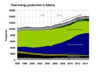
Alberta accounts for 55 per cent of Canada's oil production, or roughly 893,000 barrels per day.Natural gas heats about one-half of Canadian households, and provides about 45 per cent of the energy used by the country's manufacturing industries.Alberta accounts for just over 80 per cent of the natural gas produced in Canada – itself the world's third-largest supplier of the gas – and exports about three-quarters of its production outside the province's boundaries. About half of the five trillion cubic feet of gas produced each year in Alberta is exported to the United States, and about one-quarter flows to other points in Canada.
LLOYDMINSTER OILFIELDS Lloydminster oilfields have been operating since the 1930’s. Today there are well over 6,000 wells in the area producing in excess of 250,000 boepd. Dina Well 1937
LLOYDMINSTER OILFIELDS Some oil associated with gas Very clean formations Poorly consolidated Cretaceous sequence Deltaic sandstones Production almost always includes large amounts of formation sand Dina Well (1937)
Original heavy oil in place estimated to be over 20 billion bbls (3 billion m3).Primary recovery is estimated to be between 10 and 20%; some thermal EOR projects are achieving much higher recoveries.
A DELTAIC DEPOSITIONAL ENVIRONMENT A satellite photo of the Ganges Delta in India
Working Definition Aggressive production of sand along with heavy oil under primary production process Alternative Names Cold Flow Cold Heavy Oil Production (CHOP) Cold Production COLD HEAVY OIL PRODUCTION WITH SAND
Cold production theory states that continuous sand production is required to maintain and/or maximize oil production Initial sand production rates can be in excess of 40% by volume – this decreases over time and settles at about 1% by volume on a cold production well CHOPS
16 14 12 10 Cost per Barrel ($) CSS 8 SAGD 6 Before 1990 CHOPS 4 2 } } 0 + steam cold OPERATING COSTS Source ARC
60 50 40 Recovery (%) SAGD 30 Before 1990 20 CSS CHOPS 10 } } 0 + steam cold RECOVERY EFFICIENCY Source ARC
COLD PRODUCTION Field Oil Production Rates Source – Dr. Ron Sawatzky - ARC
250 Jan-81 Jan-85 Jan-89 Jan-93 Jan-97 Jan-01 Oil rate 200 150 Production rate (bbl/d) Start CHOPS 100 50 Water rate 0 COLD PRODUCTION PERFORMANCE Source – Dr. Ron Sawatzky - ARC
Large numbers of persistent gas bubbles in oil Generated by de-pressurization of live heavy oils Provide part of the drive for CHOPS FOAMY OIL Photo courtesy Dr. Ron Sawatzky- ARC
Reservoir Impact long wormholes in preferred, high permeability layers short lateral drainage distances to high permeability channels provide paths for CHOPS products to flow SAND PRODUCTION Photo courtesy Dr. Ron Sawatzky- ARC
WHAT IS THEHEAT DRIVEN LOOP? The Heat Driven Loop A new adaptation of existing thermosyphon heat pump technology Uses latent heat of evaporation from an evacuated, closed system to transfer heat Consists of an evaporator section and a condenser/exchanger section. Since the latent heat of evaporation is large, considerable quantities of heat can be transported quickly, efficiently, and safely.
The vaporizer and heat exchanger are evacuated The water boils at a low temperature (≈ 43°C) No air in the system reduces the risk of corrosion Operates at less than 15 psig and less than 120°C Lower temperature means lower heat loss to ambient Heat added beyond the boiling point creates low pressure, low temperature, superheated steam The steam expands into the 45’ long heat exchanger The steam condenses on the flow tube and gives up its heat to the oil in the flowtube Condensed, the steam collapses in volume and feeds by gravity back to the evaporator The expansion of the water into steam and the collapse of the steam into condensate provide the motive force THE HEAT DRIVEN LOOP
Increased heat transfer efficiency so reduced fuel requirements Lower fuel pressure at burner (< 14” WC) Eliminates direct firing of firetubes (controlled flux) – no scale – no hot spots Reduced hazards Reduced environmental risk and emissions Lower heat losses to ambient B-149.3 compliant WHAT ARE THE ADVANTAGES?
HDL APPLICATIONS Heavy Oil Production Tanks Slop Oil Treating Facilities Heavy Oil Heat Exchangers Natural Gas Line Heaters Heavy Oil Wellsite Treating
MECHANICAL PRODUCTION TREATER 45‘ heat exchanger (condenser) between well and tank 10” flowtube inside a 14” shell Auger/mixer/separator slowly turning in flowtube (≈ 1rpm) Heat supplied by the Heat Driven Loop Gas separated prior to the tank Chemical injection upstream of treater
Pilot test in “problem high sand, foamy well” 30 m3/d @ 30% (2.5%) Unable to heat past 60º Short loads due to foam Sales cut 25-30% Sales cut 2% solids High solids cut required delivery to a more distant facility PILOT 1 – LASHBURN AREA WELL
Results Significant device modifications during test – a learning process Tank is now consistently over 80º Foam problems resolved Sales cut 0.4 – 1.5% Sales cut trace solids Fuel Consumption = 84% of conventional system previously in use Oil to nearby facility Dependable Fluid Thermal Efficiency – 58% versus immersion tube efficiency of 32% PILOT 1 – LASHBURN AREA WELL
Pilot test in good well 20m3/d @ 30% (trace) Whole purpose of test was to determine if the device could consistently treat clean in a single tank PILOT 2 – LONE ROCK AREA
Consistently treats clean (<0.5% BS&W) in single tank Has been dependable and easy to operate but has had some problems with wet gas on location PILOT 2 – LONE ROCK AREA
Plant Evaluation Trial 2 MPT’s installed at a field header on a test/interim basis while waiting for a cleaning plant to be completed Test ran for ≈ 90 days Typical Oil – 74 m3/d Typical Water – 65 m3/d Average input W/C - 46% Demulsifier at 130 ppm The MPT consistently produced clean oil from sales tank ENCANA – PROVOST
ENCANA – PROVOSTPROCESS LAYOUT Mechanical Production Treaters
Slop treating facility Continuous once through process Cleaning slop and cavern material to less than 0.5% by volume Current rate is 35 m3/d (40% - 5% sand) CNRL – EAST TILL
Very efficient heat transfer. Good chemical distribution Short vertical travel distance for oil, water, and sand droplets while in flowtube Removes the gas prior to the tank (reduced turbulence in tank) No firetube related convection in the tank Augured tank cleaning reduces cleaning turbulence 10” flow tube reduces fluid velocity entering the tank Quiescence in tank WHY DOES AN MPT WORK?
MECHANICAL PRODUCTION TREATERS High Efficiency Thorough Separation Reduced Fuel Costs Reduced Chemical Costs Reduced Emissions Reduced Maintenance Costs Safe Dependable and Simple to Operate
SAND MANAGEMENT STRATEGIES Objectives Reduce waste volumes Reduce waste handling costs Reduce tank maintenance costs Minimize slop oil generation
Sand is recovered from the production tank in one of three ways: Manual Stinging Augering The recovered material is trucked to disposal TANK CLEANING
Grithog Machine – door pulls GRS Permanent Waste Recovery Systems – in plant applications and large tanks PVA – “Penetrator” Mobile Augering Technology – various SWB and pads in the field SCS SERVICES
Best option for large, flat bottom, process tanks Can clean tanks thoroughly without shutting down or contaminating the process GRS PERMANENT SAND REMOVAL SYSTEM
Economic means of tank cleaning for SWB and pads Reduces waste volume by recovering sand – not water Reduces tank upset Increases firetube life Can operate with and remove scale on the tank floor GRS PVA – “PENETRATOR” MOBILE AUGERING TECHNOLOGY
40% reduction in waste volumes due to augering in field locations Waste handling cost of $1.22/bbl versus $1.58/bbl with stinging (23% reduction) Better Water Quality – less disposal problems Less Traffic Reduced Tank Failures Fewer cleanouts – fewer loads E&P COMPANY STUDY CONCLUSIONS