Visual Guidance
Visual Guidance. Research and Development. Presented to: 34th Annual Eastern Region Airport Conference By: Donald Gallagher, Program Manager Date: March 2011. Airport Safety Technology R&D. Wildlife Hazard Mitigation Program Hazards Management, Bird Detection Radar

Visual Guidance
E N D
Presentation Transcript
Visual Guidance Research and Development Presented to: 34th Annual Eastern Region Airport Conference By: Donald Gallagher, Program Manager Date: March 2011
Airport Safety Technology R&D Wildlife Hazard Mitigation Program Hazards Management, Bird Detection Radar Aircraft Rescue and Fire Fighting Program (ARFF) Agents, Vehicles New Large Aircraft Program (NLA) Airport Issues Concerning NLA Airport Design Program Airport Design Airport Planning Program Terminal Design Guidelines, Multimodal Access Airport Surface Operations Program Runway Friction, Soft Ground Arrestor System, Runway Deicing Visual Guidance Program Lighting, Marking, Signing
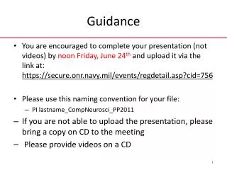
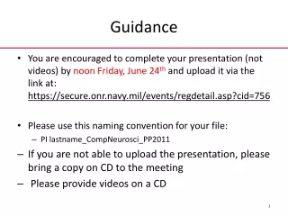
Phasing out Incandescent Lamps • The Energy Independence and Security Act of 2007 • Begins to phases out incandescent and halogen incandescent lamps in 2012 • Within five yearsan LED replacement for the PAR Type 38 halogen light will be needed The Energy Independence and Security Act of 2007 is available at:http://energy.senate.gov/public/_files/RL342941.pdf
LED Applications Issues • Does the “narrow spectral band” of LED have a negative impact to pilots with certain types of color deficient vision? • CIVIL AEROSPACE MEDICAL INSTITUTE (CAMI) andAirport Safety Technology R&D (AJP-6311) completed an evaluation on this issue sponsored by the Lighting Systems Office, AJW-46 and Office of Airport Safety and Standards, AAS-1
LEDs and Color Deficiency Issue • Approximately 8% of males and 0.5% of females in the population have congenital red-green color-deficient vision. • These people have reduced ability to discriminate redness-greenness throughout the full gamut of colors. • The problem includes the red, orange, yellow, and yellow-green parts of the visible spectrum. • Red and green are not uniformly replaced by grey. For some people with color-vision deficiency, colors like beige and yellow replace red and green.
LEDs and Color Deficiency Issue • The three main varieties of color-vision deficiency: • Protan- cannot distinguish reds and greens; reds appear dark and less bright than other colors. • Deutan-like protans, cannot distinguish reds and greens. though, there is no brightnessdeficiency. • Tritan - blues and greens are confused (less common).
LEDs and Color Deficiency Issue • Majority of color deficients are Deutans. • Results of study show using LEDsmay actually help Deutans.
Runway Guard Lights. Touchdown zone. Runway Edge including Threshold, End lights and Stopways. Signs per location. Taxiway curved segments (centerline and edge). Approach Light System. Stop Bar. Runway Centerline. Rapid Exit Taxiway Indicator Lights (RETIL) (up until the holding position or runway vacated position). Intermediate holding position. Precision Approach Path Indicator (PAPI) How will this technology interact if interspersed with standard incandescent lights? Define what “system(s)” are not to be interspersed.
How will this technology interact with present airport systems? • Established a Electrical Infrastructure Research Team (EIRT) • A team of FAAand Industryexperts to design an Airport Lighting Infrastructure to take full advantage of new lighting technologies.
How will this technology interact with present airport systems? • Circuit designs considered so far: • 450 V, AC Parallel Circuit • 1.4 Amp, DC Series Circuit • 2.8 Amp, AC Series Circuit • PWM, DC Series Circuit • Preparing small scale testing of these circuits.
Claim: LEDs can not be seen with Night Vision Goggles! True or False? FALSE! What lights are seen is not based on the lighting technology. It is based on what spectrumthe NVG technology uses. NVGs have either Type A or B filterswhich changes thespectrum sensed.
Night Vision Goggles • Commonly used Gen 3 NVGs sensitivity range is from approx. 450nm to 920nm. • Commonly produced LEDs are from 460nm for Blueto 645nmfor Red. • NVG Gen3 without filterswill respond to Green, Yellow, and Red LEDs.
Night Vision Goggles • Class A filters respond at wavelengths longer than 620nm and Class B at 640nm. • With class Afilters it will respond to red LEDs. • With class Bfilters no LEDsand some incandescent in the colorslisted will cause a visual response.
Night Vision Goggles L-810 LED Red Obstruction Light from 60 ft using NVGs with Class A filter
Recommendations • These values can be obtained by a combination of a selectingasquare wavesignal,flash rate,andon-time percentage. • The best flash rates & on-time percentages were: 1.25 Hz@70%or2.50 Hz@30%
Moving Forward Prototype LED ERGLs have been constructed based on the lab study that will: Compatible with typical airport electrical infrastructures. Ability to provide 90, 135, and 180 flashes per minute, with a square wave at a duty cycle of 30%and 70%(selectable for evaluation). Ability to provide a minimum average intensity of90 Cdat Step 1 dimming (10%) and 900 Cd for Step 3 (100%). Field testing at Daytona Int’l Airport in 2011.
Holding Position Signs for Runway Approach Areas • ATO is in the process of revising their current procedure, which does not requirepilots to obtain a specific clearanceto cross these holding markings. • In the revised procedures Pilots will now be required to obtain specific clearance to pass any holding position marking/signing.
Holding Position Signs for Runway Approach Areas • The RSO has identified a potential risk of runway incursions due to pilot confusion at the holding position marking and signs for a runway approach. • ATO would like to retaintheir current practice - consistency therefore a different marking andsigning may be required.
Holding Position Signs for Runway Approach Areas • Additionally, current signing identifies the protected areaas an"approach" with the corresponding runway designation. • In practice, the protected areais also associated with departures from the reciprocal runway. • Potential exists for confusionif pilots and/or air traffic controllers must refer to the approach to a runway in verbal communications when operationsare actually departures on the reciprocal runway.
Standard Mandatory Sign WhenHold is Required 15 - APCH
Standard Mandatory Sign WhenHold is NOTRequired 15 - APCH 1st ChangeStandard Hold Line Marking To Conditional Hold Line Marking (ILS/MLS) for Approach areas
Standard Mandatory Sign When Hold is NOTRequired 15 - APCH 15 - APCH And possibly ChangeSign from RED To GREEN
Holding Position Signs for Runway Approach Areas • Status • Obtaining Quotes from LED sign manufacturers to build prototype sign.
Automatic Switching technologies for Rwy Centerline Lights in a Displaced Threshold • The FAA Advisory Circular AC 150/5340-30D “Design and Installation details for Airport Visual Aids” states: • “For displaced thresholdareas over 700 feet(100m) in length and used for takeoffs, the centerline lightsin the displaced areaare circuited separately from the centerline lights in the non-displaced runway area to permit turning “off” the centerline lightsin the displaced areaduring landing operations.” • Teterboro Airport has this issue on both ends of runway 1/19. • Air Traffic Control are indisposed to operating the interlock switch that manually controls the centerline lights.
Project Objectives • Evaluate and determine the feasibility of using varied surveillance technologiesand safety logic to automate the activation/deactivationof RunwayCenterline Lightingin a displaced threshold to support takeoff/landing operations. • Install and optimize the preferred technology at Teterboro Airport (TEB)
Solution Architecture Surveillance of the area of interest is derived from a surveillance element Light activation logic determines if centerline lights should be activated.Light commands are sent to field lighting system
Conclusions • The tests and evaluations proved that localized surveillance technologies and coupled safety logic are viable to automate the activation/deactivation of lights in a displaced threshold runway environment to support takeoff/landing operations. • Operational concepts and performance requirementswere developed for a runway light automation system harnessing localized surveillance sensors to support the use of the system at civil airports.
Principal Requirements The sensors shall be located to allow for an unobstructed view of the displaced threshold area. The sensors shall be placed within 550 feet of the displaced threshold area. The sensors shall be mounted on a stable structure A permanent operational deployment shall include for a phase-in period to allow testing of 2000 movements.
Mitigation Strategies/Recommendations The system support equipment shall be situated in an operating environment with Temperature: 20 to 30ºC derating 1.0ºC per every 1000ft above sea level.Maximum rate of change: 10ºC/hrHumidity: 20-80% relative non-condensingNo direct sustained sunlight Ancillary functional and performance requirements will be disclosed in impending regulatory guidance
Low-Cost Ground Surveillance Specification Development
Mission To enhance airport operations by improving safety, shared situational awareness & environmental impact, reducing airport operating costs and improving capacity and resource utilization The LCGS Project Scope • Develop FAA functional and operationalstandards for LCGS implementation that would support AIP eligibility for this system. • Provide the foundational capability to support other runway safety improvements (e.g. RWSL, dynamic stop bar automation, …). • Develop a cost-benefits case for the use of Low Cost Ground Surveillance Systems for airport operations.
LCGS Challenge • Of over 460 towered airportsin the NAS only 35 of the larger airports have or are slated to receive comprehensive surface surveillance systems (i.e. ASDE-X). • Many of the excluded small to mid-sized airports have considerable surveillance needs that are not being met. • Surveillance capacity is limited to voice reporting and field of view • Many of today’s airports struggle with the challenge of improving operational efficiency and maximizing revenue growth opportunities.
LCGS High Level Concept • The currentlydevelopedLCGS solution is centered on the use of a Surface Movement Radar (SMR) to monitor ground traffic movements. • SMR inherently presents some deficiencies (loss of target due to masking, plot clutter due to rain or grass reflection, flight label overlap, etc.) which renders the surveillance function less effective and could result in a lack of confidence in the system. • SMR technology is characterized by high maintenance and lifecycle costs.
LCGS High Level Concept • Researching existing technology the framework recommended for an LCGS system is the coupling of a network of non-cooperative (i.e. optical and thermal devices) sensors and a Mode S multilateration system. • This will provide the most flexibleand modular framework for the smaller airports as multilateration systems can be easily adapted to smaller coverage areas with complex layouts and no vertical extension. • This network design would provide several levels of redundancy which would translate into continuous operational availability and coverage.
Status • Concluded final preliminary study on strengths,limitationsand cost effectiveness of prospective systems. • Conducting site visitsto deployment locations of prospective systems. • Work in concert with the Advanced Technologies Development & Prototyping Group (AJP-67) at the three approved test sites of San Jose Airport (SJC), Long Beach Airport (LGB) and Manchester-Boston Regional Airport (MHT). - Test candidate systems against predefined functional requirements. - Evaluate operational feasibility of candidate systems.
General Aviation • For non-part 139 airports • Lighting small airports that do not qualify for AIP funds. • “COMMUNITY SERVICE AIRPORT LIGHTING HANDBOOK” posted on Illuminating Engineering Societies Aviation Lighting Committee's (IESALC) web site. http://iesalc.org/subcommittees_genaviation.html
Final Approach & TakeOff (FATO) area Heliport Approach Path Indicator (CHAPI) Heliport Instrument Landing System (HILS) for IMC Touchdown & Lift Off (TLOF) area Heliport Approach Lighting System (HALS) for IMC Vertical Flight Current Facility
Vertical Flight • Conducting photometric tests on products being sold as heliport perimeter lights. • Intensity • Beam spread • Chromaticity • Currently conducting flight test • To determine if a suitable candidate exists.
Research Runway Cape May County Airport( KWWD) Cape May County Airport Delaware River Bay Authority
Cape May County Airport( KWWD) Research Runway Runway 10/28 - 4,998 x 150 ft. Runway 1/19 - 4,998 x 150 ft. Cape May County Airport( KWWD)
New Visual Guidance Technology Test Bed • Will be conducted in three phases funded over a three year period. • Phase 1: • To be Completed: • Layout plan. • Schedule of installation. • Begin refurbishment of unused runway pavement. • Begin electrical infrastructure installation. • Currently developing an MOAwith the Delaware River and Bay Authority (DRBA) for the use of Cape May Airport.
Questions or Comments? Donald.Gallagher@faa.gov – Visual Guidance Program Manager FAA Technical Center Airport Safety Technology R&D Section AJP-6311, AAR-411, Building 296 Atlantic City International Airport, NJ 08405 www.airporttech.tc.faa.gov