CCNA 3 v3.0 Module 7 Spanning Tree Protocol
220 likes | 627 Vues
CCNA 3 v3.0 Module 7 Spanning Tree Protocol. Purpose of This PowerPoint. This PowerPoint primarily consists of the Target Indicators (TIs) of this module in CCNA version 3.0. It was created to give instructors a PowerPoint to take and modify as their own. This PowerPoint is:

CCNA 3 v3.0 Module 7 Spanning Tree Protocol
E N D
Presentation Transcript
Purpose of This PowerPoint • This PowerPoint primarily consists of the Target Indicators (TIs) of this module in CCNA version 3.0. • It was created to give instructors a PowerPoint to take and modify as their own. • This PowerPoint is: • NOT a study guide for the module final assessment. • NOT a study guide for the CCNA certification exam. • Please report any mistakes you find in this PowerPoint by using the Academy Connection Help link.
To Locate Instructional Resource Materials on Academy Connection: • Go to the Community FTP Center to locate materials created by the instructor community • Go to the Tools section • Go to the Alpha Preview section • Go to the Community link under Resources • See the resources available on the Class home page for classes you are offering • Search http://www.cisco.com • Contact your parent academy!
Objectives • Redundant topologies • SpanningTree Protocol
Redundancy Redundant networking topologies are designed to ensure that networks continue to function in the presence of single points of failure.
Redundant Topologies • A goal of redundant topologies is to eliminate network outages caused by a single point of failure. • All networks need redundancy for enhanced reliability.
Media Access Control Database Instability In a redundant switched network, it is possible for switches to learn the wrong information. A switch can learn that a MAC address is on a port when it is not.
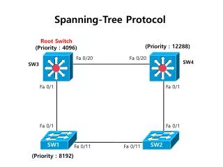
Spanning-Tree Operation • One root bridge per network. • One root port per nonroot bridge. • One designated port per segment. • Nondesignated ports are unused.
Bridge Protocol Data Unit Bridge protocol data unit (BPDU)
Spanning-Tree Recalculation A switched internetwork has converged when all the switch and bridge ports are in either the forwarding or blocked state.
Rapid Spanning-Tree Protocol • The standard and protocol introduce the following: • Clarification of port states and roles • Definition of a set of link types that can go to forwarding state rapidly • Allowing switches, in a converged network, to generate their own BPDUs rather than relaying root bridge BPDUs
Rapid Spanning-Tree Port Designations The Rapid SpanningTree Protocol, IEEE 802.1w, will eventually replace the SpanningTree Protocol, IEEE 802.1D.