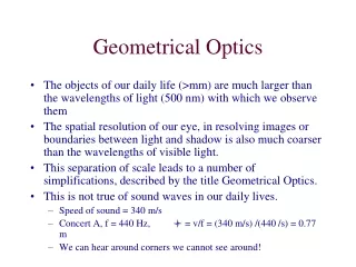
Geometrical Optics
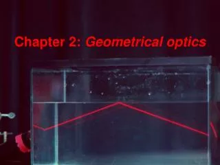
Chapter 24. Geometrical Optics. Optical fibers. Total internal reflection is used in fiber optics Optical fibers are composed of specially made glass and used to carry telecommunication signals These signals are sent as light waves They are directed along the fiber using internal reflection.

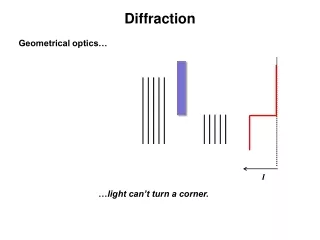
Geometrical Optics
E N D
Presentation Transcript
Chapter 24 Geometrical Optics
Optical fibers • Total internal reflection is used in fiber optics • Optical fibers are composed of specially made glass and used to carry telecommunication signals • These signals are sent as light waves • They are directed along the fiber using internal reflection
Dispersion • different colors have different wavelengths • the speed of light in a material is different depending on the color • this dependence of wave speed on color is called dispersion • Since the index of refraction is slightly different for each color, the angle of refraction will be different for each color • (greater n, thus more light kinking for blue than for red) • In gemology dispersion is called “fire”
Dispersion and Prisms • In a prism, a beam of white light is dispersed into its component colors • There are two refractions at 2 prism surfaces • Red and blue show the extremes of the dispersed beam
Curved Mirrors • A curved mirror can produce an image of an object that is magnified • The image can be larger or smaller than the object • Magnified images are used in many applications • Telescopes • Rear view mirrors in cars • Many others
Demo: flat, convex, concave mirror convex mirror concave mirror flat mirror
Ray Tracing – Curved Mirror • A spherical mirror is one in which the surface of the mirror forms a section of a spherical shell • The radius, R, of the sphere is the radius of curvature of the mirror • The mirror’s principal axis is the line that extends from the center of curvatureto the center of the mirror
Concave Spherical Mirror • Properties of concave spherical mirrors • Incoming rays that are close to and parallel to the principal axis reflect through a single point F • F is the focal point • It is located a distance ƒ, the focal length, from the mirror • Rays that originate at the focal point reflect from the mirror parallel to the principal axis • From reversibility of light Demo: IR mirrors
Image from Concave Mirror – Ray Diagram • Trace rays emanating from the top of the object • The rays all intersect at a single point • This is the top of the image • A similar result would be found from rays from other parts of the object
3 easy rays • Three rays are particularly easy to draw • There are an infinite number of actual rays • The focal ray • From the tip of the object through the focal point • Reflects parallel to the principal axis • Focal ray • Parallel ray • Central ray
3 easy rays • The parallel ray • From the tip of the object parallel to the principal axis • Reflects through the focal point • The central ray • From the tip of the object through the center of curvature of the mirror • Reflects back on itself • The three rays intersect at the tip of the image
Properties of an Image • Magnification is the ratio of the height of the image, hi, to the height of the object, ho • By convention, the image height of an inverted image is negative • Therefore, the magnification is also negative • Images smaller than the object are said to be reduced
Real vs. Virtual Images • If the rays that form the image all pass through a point on the image, the image is called a realimage • Real images and virtual images differ • Light rays only appear to emanate from a virtual image, they do not actually pass through the image • For a real image, the light rays really pass through the image • An object and its real image are both on the same side of the mirror • A virtual image is located behind the mirror while the object is in front
Concave Mirror and Virtual Images • Use ray tracing to find the image when the object is close to the mirror • Closer than the focal point • Use the same three easy rays: focal, parallel, central rays • The rays do not intersect at any point in front of the mirror
Virtual Images • Extrapolate the rays back behind the mirror with dashed lines • They intersect at a single image point • The rays appear to emanate from the image point behind the mirror • The image is virtual because light does not actually pass through any point on the image • The object and its image are on different sides of the mirror • The image is upright and enlarged
Ray Tracing – Convex Spherical Mirrors • A mirror that curves away from the object is called a convex mirror • The center of curvature and the focal point lie behind the mirror • After striking the convex surface, the reflected rays diverge from the mirror axis • The parallel rays converge on an image point behind the mirror • This is the focal point, F
Ray Tracing – Convex Spherical Mirror • The same three rays are used as were used for the concave mirror • The focal ray is directed toward the focal point but is reflected at the mirror’s surface, so doesn’t go through F • The three rays extrapolate to a point behind the mirror • Produces virtual image
Mirror Equation • Geometry can be used to find the characteristics of the image quantitatively • The distance from the object to the mirror is so • The distance from the image to the mirror is si • The rays produce similar triangles
Mirror Equation and Focal Length • From the similar triangles, • For an object at infinity, 1/so = 0 • But an object at infinitywill produce parallel rays • Parallel rays all intersect at the focal point • Therefore, the focal length can be found from the radius of curvature of the mirror
Mirror Equation and Magnification • The mirror equation can be written in terms of the focal length • The magnification can also be found from the similar triangles shown in fig. 24.30
Sign Conventions • All diagrams with mirrors should be drawn with the light ray incident on the mirror from the left • The object distance is positive when the object is to the left of the mirror and negative if the object is to the right (behind) of the mirror • The image distance is positive when the image is to the left of the mirror and negative if the image is to the right (behind) of the mirror • The image distance is positive for real images and negative for virtual images
Sign Conventions, cont. • The focal length is positive for a concave mirror and negative for a convex mirror • For a concave mirror, ƒ = R / 2 • For a convex mirror, ƒ = - R / 2 • The object and image heights are positive if the object/image is upright and negative if it is inverted
Problem 24.48 A convex mirror has a focal length of -20 cm. where is the image if it is upright and one fourth the size of the object?