Download
1 / 51
530 likes | 704 Vues
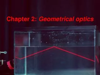
Explore the principles of geometrical optics in understanding the behavior of light, reflection, and image formation with mirrors, shadows, and apertures. Learn about wavefronts, rays, and the properties of different types of mirrors.

E N D
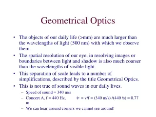
Geometrical Optics • The objects of our daily life (>mm) are much larger than the wavelengths of light (500 nm) with which we observe them • The spatial resolution of our eye, in resolving images or boundaries between light and shadow is also much coarser than the wavelengths of visible light. • This separation of scale leads to a number of simplifications, described by the title Geometrical Optics. • This is not true of sound waves in our daily lives. • Speed of sound = 340 m/s • Concert A, f = 440 Hz, l = v/f = (340 m/s) /(440 /s) = 0.77 m • We can hear around corners we cannot see around!
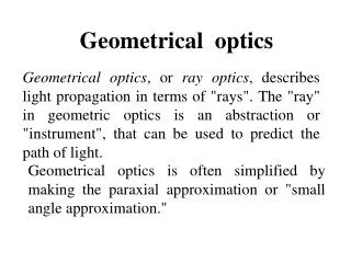
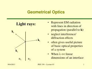
Geometrical Optics In describing the propagation of light as a wave we need to understand: wavefronts: a surface passing through points of a wave that have the same phase. rays: a ray describes the direction of wave propagation. A ray is a vector perpendicular to the wavefront.
Light Rays • The propagation of the wavefronts can be described by light rays. • In free space, the light rays travel in straight lines, perpendicular to the wavefronts.
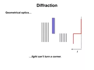
Shadows • In geometrical optics, apertures cast sharp shadows Light rays from point source screen
Image formation with a Pinhole camera Light source Dark room = Camera obscura Object Image do = distance from object to pinhole di = distance from pinhole to image ho = height of object hi= height of image Image is fuzzy if pinhole is larger Image is sharper if pinhole is smaller Image is dimmer is pinhole is smaller
Fuzziness of image from size of pinhole Light source Dark room = Camera obscura • A larger pinhole brings in more light, but produces a fuzzy image. Object Image
Reflection and Refraction When a light ray travels from one medium to another, part of the incident light is reflected and part of the light is transmitted at the boundary between the two media. The transmitted part is said to be refracted in the second medium. incident ray reflected ray refracted ray
Types of Reflection If the surface off which the light is reflected is smooth, then the light undergoes specular reflection (parallel rays will all be reflected in the same directions). If, on the other hand, the surface is rough, then the light will undergo diffuse reflection (parallel rays will be reflected in a variety of directions)
The Law of Reflection For specular reflection the incident angle qi equals the reflected angle qr: qi=qr The angles are measured relative to the normal, shown here as a dotted line.
Forming Images with a Plane Mirror A mirror is an object that reflects light. A plane mirror is simply a flat mirror. Consider an object placed at point P in front of a plane mirror. An image will be formed at point P´ behind the mirror. do = distance from object to mirror di = distance from image to mirror ho = height of object hi= height of image hi ho do di For a plane mirror: do = -diand ho = hi Image is behind mirror: di< 0
Images An image is formed at the point where the rays of light leaving a single point on an object either actually intersect or where they appear to originate from. If the light rays actually do intersect, then the image is a real image. If the light only appears to be coming from a point, but is not physically there, then the image is a virtual image. We define the magnification, m, of an image to be: If m is negative, the image is inverted (upside down).
Plane Mirrors A plane mirror image has the following properties: • The image distance equals the object distance ( in magnitude ) • The image is unmagnified • The image is virtual: • negative image distance • di < 0 • m>0, The image is not inverted do di
To save expenses, you would like to buy the shortest mirror that will allow you to see your entire body. Should the mirror be • half your height • two-thirds your height, or • equal to your height?
To save expenses, you would like to buy the shortest mirror that will allow you to see your entire body. Should the mirror be • half your height • two-thirds your height, or • equal to your height?
To save expenses, you would like to buy the shortest mirror that will allow you to see your entire body. Should the mirror be half your height two-thirds your height, or equal to your height? • Does the answer depend on how far away from the mirror you stand? • Yes b) No
To save expenses, you would like to buy the shortest mirror that will allow you to see your entire body. How tall should the mirror be? Does the answer depend upon the distance from your eyes to the top of your head? a) Yes b) No
To save expenses, you would like to buy the shortest mirror that will allow you to see your entire body. How tall a mirror do you need? Does the answer depend upon how high you hang the mirror? a) Yes b) No
Spherical Mirrors concave A spherical mirror is a mirror whose surface shape is spherical with radius of curvature R. There are two types of spherical mirrors: concave and convex. We will always orient the mirrors so that the reflecting surface is on the left. The object will be on the left. convex
Focal Point When parallel rays (e.g. rays from a distance source) are incident upon a spherical mirror, the reflected rays intersect at the focal point F, a distance R/2 from the mirror. (Locally, the mirror is a flat surface, perpendicular to the radius drawn from C, at an angle q from the axis of symmetry of the mirror). For a concave mirror, the focal point is in front of the mirror (real). For a convex mirror, the focal point is behind the mirror (virtual). The incident rays diverge from the convex mirror, but they trace back to a virtual focal point F.
A Focal Length The focal lengthf is the distance from the surface of the mirror to the focal point. CF = FA = radius = FM M The focal length FM is half the radius of curvature of a spherical mirror. Sign Convention: the focal length is negative if the focal point is behind the mirror. For a concave mirror, f = ½R For a convex mirror, f = ½R (R is always positive)
Ray Tracing It is sufficient to use two of four principal rays to determine where an image will be located. M ray The parallel ray (P ray) reflects through the focal point. The focal ray (F ray) reflects parallel to the axis, and the center-of-curvature ray (C ray) reflects back along its incoming path. The Mid ray (M ray) reflects with equal angles at the axis of symmetry of the mirror.
Ray Tracing – Examples Put film here for Sharp image. concave convex Virtual image Real image
The Mirror Equation Sign Conventions: do is positive if the object is in front of the mirror (real object) do is negative if the object is in back of the mirror (virtual object) diis positive if the image is in front of the mirror (real image) di is negative if the image is behind the mirror (virtual image) f is positive for concave mirrors f is negative for convex mirrors m is positive for upright images m is negative for inverted images The ray tracing technique shows qualitatively where the image will be located. The distance from the mirror to the image, di, can be found from the mirror equation: do = distance from object to mirror di= distance from image to mirror f = focal length m = magnification
Example 1 An object is placed 30 cm in front of a concave mirror of radius 10 cm. Where is the image located? Is it real or virtual? Is it upright or inverted? What is the magnification of the image? di>0 Real Image m = -di / do = -1/5
Example 2 An object is placed 3 cm in front of a concave mirror of radius 20 cm. Where is the image located? Is it real or virtual? Is it upright or inverted? What is the magnification of the image? Virtual image, di <0 Magnified, |m| > 1, not inverted. m > 0
Example 3 An object is placed 5 cm in front of a convex mirror of focal length 10 cm. Where is the image located? Is it real or virtual? Is it upright or inverted? What is the magnification of the image? Virtual image, di <0 De-Magnified, |m| < 1, not inverted. m > 0
Example 4 A concave mirror produces a virtual image that is three times as tall as the object. (a) If the object is 22 cm in front of the mirror, what is the image distance? (b) What is the focal length of this mirror?
The Refraction of Light The speed of light is different in different materials. We define the index of refraction,n,of a material to be the ratio of the speed of light in vacuum to the speed of light in the material: n = c/v When light travels from one medium to another its velocity and wavelength change, but its frequency remains constant. If a dielectric medium has dielectric constant k, then • v = 1/(ke0m0)1/2 = • n = 1/k
q1 Air Glass q2 Snell’s Law In general, when light enters a new material its direction will change. The angle of refraction q2is related to the angle of incidenceq1 by Snell’s Law: where v is the velocity of light in the medium. Snell’s Law can also be written as n1sinq1 = n2sinq2 Normal line Theangles q1 and q2 are measured relative to the line normal to the surface between the two materials. Principle of least time
Which of these rays can be the refracted ray? water Heavy glass n1sinq1 = n2sinq2 n = 1.3 n = 2 a) [c) Is straight ahead] b) c) d)
Which way will the rays bend?Which of these rays can be the refracted ray? [c) Is straight ahead] n1sinq1 = n2sinq2 n = 1.6 n = 1.2 d) c) a) b)
Example You have a semicircular disk of glass with an index of refraction of n = 1.52. Find the incident angle q for which the beam of light in the figure will hit the indicated point on the screen. 1 sin(q) = n sin(q1) = n (5cm)/[(5cm)2+(20cm)2]1/2 = (1.52)(5)/20.62=0.369 q = 21.6 deg
Total Internal Reflection When light travels from a medium with n1 > n2, there is an angle, called the critical angle qc, at which all the light is reflected and none is transmitted. This process is known as total internal reflection. The critical angle occurs when q2= 90 degrees: Total internal reflection if sinq2>1 The incident ray is both reflected and refracted. Total Internal Reflection
A ray of light enters the long side of a 45°-90°-45° prism and undergoes two total internal reflections, as indicated in the figure. The result is a reversal in the ray’s direction of propagation. Find the minimum value of the prism’s index of refraction, n, for these internal reflections to be total. Example
Lenses Light is reflected from a mirror. Light is refracted through a lens.
Focal Point The focal point of a lens is the place where parallel rays incident upon the lens converge. diverging lens converging lens
Ray Tracing for Lenses Just as for mirrors we use three “easy” rays to find the image from a lens. The lens is assumed to be thin. The P ray propagates parallel to the principal axis until it encounters the lens, where it is refracted to pass through the focal point on the far side of the lens. The F ray passes through the focal point on the near side of the lens, then leaves the lens parallel to the principal axis. The M ray passes through the middle of the lens with no deflection (in thin lens limit).
M ray As the thickness of glass decreases to zero, so does the sideways displacement
The Thin Lens Equation The ray tracing technique shows qualitatively where the image from a lens will be located. The distance from the lens to the image, di, can be found from the thin-lens equation: Sign Conventions: do is positive for real objects (from which light diverges) do is negative for virtual objects (toward which light converges) diis positive for real images (on the opposite side of the lens from the object) di is negative for virtual images (same side as object) f is positive for converging (convex) lenses f is negative for diverging (concave) lenses m is positive for upright images m is negative for inverted images
Example 4 An object is placed 20 cm in front of a converging lens of focal length 10 cm. Where is the image? Is it upright or inverted? Real or virtual? What is the magnification of the image? Real image, magnification = -1
Example 5 An object is placed 5 cm in front of a converging lens of focal length 10 cm. Where is the image? Is it upright or inverted? Real or virtual? What is the magnification of the image? Virtual image, as viewed from the right, the light appears to be coming from the (virtual) image, and not the object. Magnification = +2
Example 6 An object is placed 8 cm in front of a diverging lens of focal length 4 cm. Where is the image? Is it upright or inverted? Real or virtual? What is the magnification of the image?
Walker Problem 69, pg. 885 (a) Determine the distance from lens 1 to the final image for the system shown in the figure. (b) What is the magnification of this image? When you have two lenses, the image of the first lens is the object for the second lens.
Two Lenses First lens Image 2nd Lens
Dispersion In a material, the velocity of light (and therefore the index of refraction) can depend on the wavelength. This is known as dispersion. Blue light travels slower in glass and water than does red light. As a result of dispersion, different colors entering a material will be refracted into different angles. Dispersive materials can be used to separate a light beam into its spectrum (the colors that make up the light beam). Example: prism
The Rainbow No two people ever see the same rainbow