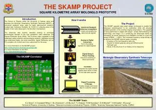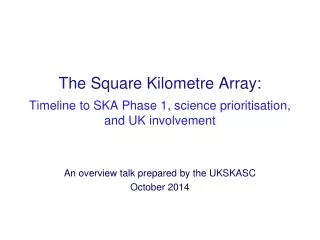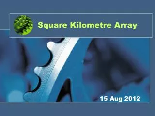
Square-Kilometre Array
Square-Kilometre Array. The Next Generation Radio Telescope http://www.atnf.csiro.au/SKA Dr Peter J Hall Australia Telescope National Facility CSIRO SKA Program Leader. Presentation Outline. Radio astronomy and radio telescopes Motivation for building the SKA SKA concept and design goals


Square-Kilometre Array
E N D
Presentation Transcript
Square-Kilometre Array The Next Generation Radio Telescope http://www.atnf.csiro.au/SKA Dr Peter J Hall Australia Telescope National Facility CSIRO SKA Program Leader
Presentation Outline • Radio astronomy and radio telescopes • Motivation for building the SKA • SKA concept and design goals • key characteristics • Ideas for SKA realization • reflectors, arrays, lenses, signal processing • interference mitigation • site selection • Design and technology challenges • Australian and international aspects of the SKA project
Radio Astronomy • Begun in 1930s by Karl Jansky - a Bell Labs communications engineer • Developed in 1940s by Grote Reber, a US radio engineer and radio amateur • Became respectable in late 1940s. Australia was an early player and has remained a world leader • Has provided insight into the most fundamental questions, e.g. • 3 K big bang background radiation (communications engineers again) • general relativity (binary pulsars) • Gives access to physical conditions unattainable in labs • Australia is good at astronomy, and RA in particular • DISR impact studies
Radio Astronomy • RA derives information about the Universe from the study of natural radiation in the range ~ 10 MHz - 1000 GHz • Radio telescopes use the combination of an antenna and receiver to form a radiometer - a device for measuring the radiation temperature of a distant region of space viewed by the antenna beam • The received radiation may be continuum (broadband noise) or spectral line (“quasi-cw”) in character; variation on timescales of milliseconds to years may be involved • The measured temperature may or may not be the physical temperature of the region, depending on whether the emission is thermal or non-thermal
Radio Telescopes • Can be: • single continuous aperture (e.g. parabolic dish) • focussing (wavefront delay) done optically • synthesized aperture (e.g. array) • focussing done using time delay electronics • can make huge effective aperture • mathematically manipulate wave interference patterns between array elements to simulate continuous aperture • Sensitivity depends on total collecting area of aperture • Angular resolution depends on linear extent of aperture (micro-arcsecond attainable) • Typically use very low-noise receivers (e.g. cryogenically cooled)
$$$ Computer Dishes and Arrays New paradigm: wavefront sensors and software replace steel (Steel) Physical Aperture $$$ (computers) Synthesized Aperture
Major ATNF Radio Telescopes • 64 m Parkes dish; 6 x 22 m AT Compact Array; both upgraded substantially to maintain international competitiveness
Radio Images Using the ATCA SN1987a NGC1808 PKS2356-61
Radio Telescopes of the Future • HEMT receivers • Wide-band, cheap, small and reliable • Need to build low-noise systems with many elements • Focal planes arrays • N beams => N-fold increase in telescope speed (and data rate!) • Greatly improve calibration schemes and imaging dynamic range • Synthesised beams and illumination patterns to overcome problems of feed packing • Interference rejection • Adaptive nulling and RFI cancelling can work in single dishes and arrays • More computing capacity • Computing power doubles every 18 months (Moore’s Law) • Era of software-defined radio telescopes is upon us
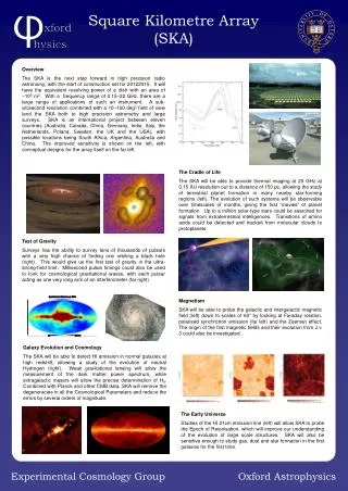
Square Kilometer Array - Why? • Current large telescope technology dates from 1960/70’s • VLA total area ~ 104 m2 • Era of facilities upgrades approaching its end • Large increase in sensitivity is needed (100x), telescopes not receiver noise limited ==> 1 km2 collecting area • epoch of first stars and galaxies • major advance in many other areas of astronomy (and hence physics) • New challenges: • cost ($US600 m cf ~ $US50 m for ATCA) • frequency coverage • man-made interference • completion by ~2010 • Technology shift will be required
Core Issue HST VLA
Solution HST SKA
Astronomy Beyond the Light COBE satellite NASA “Primordial soup” - matter and energy radio ? Square-Kilometre Array “Dark Ages” - before the stars Early galaxies - stars light up light Hubble Space Telescope NASA / ESA
SKA: Selected “Other” Astronomy • Active Galactic Nuclei • does every ‘normal’ galaxy contain a black hole? • Magnetic fields • Faraday rotation studies of Milky Way, intergalactic medium and nearby galaxies • Radio emission from hot and cool stars • including imaging surfaces and atmospheres of giant stars • Radio after-glows of gamma-ray bursts • merger of a neutron star pair? • Pulsars • first demonstrated existence of extra-solar planets and gravitational waves; explicit demonstrations of general relativity • future use in timing standards; interplanetary navigation; cosmological background of gravity waves • Deep space network tracking; SETI
SKA: The Concept • One square km radio telescope (SKA) in 2010 • 2005 technology choice • 2007 construction • 2012 operations • Frequency range 0.3 - 12 GHz (minimum) • Sensitivity 100 x VLA • need ~ 68 dB K-1 at 1.4 GHz • Multibeam essential at lower frequencies • Need innovative design to reduce cost • International funding unlikely to exceed $US600m • 106 sq metre => ~$500 / sq metre • cf VLA $10,000 / sq metre • GMRT $1,000 / sq metre
1kT 20cm 1kT 6cm HST FOV mmA FOV SKA Key CharacteristicsField of View 20 Mpc at z = 0.3
SKA Key CharacteristicsConfiguration 20 km Array Station 200 km
SKA Key CharacteristicsMultibeaming 16 Synthesized beams 12 Station antenna patterns 8 Element antenna pattern 4 NFRA 1998
SKA - Multiple Station Concept 1000km (Courtesy NFRA)
Large Reflector SKA • Need revolution in construction technique before conventional large steerable dishes could be used • Chinese have suggested multiple Arecibo (‘holes in ground’) approach
Luneburg Lens Focussing • Plane waves incident from left • 1 m diameter lens, 2 GHz radiation • Classical Luneburg - focus on surface (Image courtesy Dr Andrew Parfitt, CTIP)
SKA Signal Processing - Reality Check • Can we expect to be able to process the signals from an array as vast as the SKA? • Look at the growth in computation power per unit (area, dollar…) • familiar as Moore’s Law
Moore’s Law - Astronomical Correlators Year (Roughly doubles every two years)
SKA Signal Processing - Rough Guide • To correlate 106 antennas, over a 500 MHz bandwidth, with 104 frequency channels needs ~ 1012 Giga ops/sec • In 2010 astronomical correlators will be capable of ~107 Giga ops/sec • must aggregate SKA antennas prior to correlation • can only correlate ~4000 ‘elements’ • with 100 stations, each station can have ~40 clusters of antennas • with 400 Luneburg Lens station, combine 10 lenses per cluster • If we wait until 2020, can reduce aggregation by ~3 • but only if Moore’s Law holds!
SKA - Interference Mitigation • Why? • SKA needs to observe outside (small) designated astronomy bands to meet its scientific objectives • SKA sensitivity is unprecedented (~100 times VLA) • each beam ~ 10mJy in 1 sec OR ~ -265 dBW/m2/Hz (128 MHz continuum bandwidth) • terrestial transmissions will be a problem for all but a few sites on Earth • satellite transmissions are now globally pervasive (intentional constellation coverage for many LEOs) • How? • No single IM solution; need a hierarchy of techniques starting with telescope site and environment, and ending with astronomy data processing
Terrestrial Interference FORTÉ satellite: 131 MHz
Global InterferenceFrom The Sky - An Example These peaks also change frequency as the satellite moves across the sky Signal levels of brightest* celestial radio sources Signal strength ITU permitted average level MHz ITU frequency allocation to Radio Astronomy * Signals from early Universe are 100 billion times weaker IRIDIUM satellite: measured 1998
SKA Interference Mitigation Essentials • Effective • Robust • Versatile: different observing modes, different techniques (or different emphases in hierarchy) • e.g. snapshot versus synthesis imaging modes; pulsar modes • Low toxicity • removing the interference must not ruin the astronomy data, nor turn easy-to-identify spurious signals into hard-to-identify artifacts • bear in mind the imaging dynamic range needed in the SKA is >106 so uncorrected fiddling with imaging beams may be disastrous
SKA Interference Mitigation Hierarchy • Location of instrument (esp. central cluster), and legislated or regulated radio quiet zone • Array configuration (use power of correlation processing for as much critical science as possible) • Choice of concentrators and feeds • Design of (cheap) high-intercept MMIC low-noise amplifiers • Placement of RF/IF filters for high-level, fixed frequency RFI (e.g. photonic fibre filters) • “High” resolution quantizers and first-level digital filters • DSP adaptive techniques (exploiting SKA buffer?) • New image and time-domain processing techniques
AT Compact Array data Russian GLONASS satellite + two frequency markers + astronomy signal in passband Off-line digital adaptive filtering by Steve Ellingson, Electrosciences Lab OSU On-line (real-time) realizations possible Much synergy with military and commercial users Practical Interference Mitigation
SKA Critical Design Challenges • Wide bandwidth • antenna element type; use of true time delay phasing • Sensitivity • how to maintain effective area of antennas with frequency variation • Cost • need highly-integrated, easily manufactured systems • Interference mitigation • telescope site, adaptive RF, photonic and digital techniques • Calibration • 106 dynamic range; good polarization purity; both in presence of adaptive beaming! • Upgrade path • expensive infrastructure must last well; need to follow Moore’s Law (or equiv.) • Operations • robust; maintainable; advanced power generation and management
SKA Critical Technologies • Antennas & feeds • wideband, multi-beaming, easily manufactured, cheap • specific CSIRO challenge to make a cheap Luneburg Lens • RF front-ends • low-noise, ambient temperature, very highly integrated • Signal transmission and distribution • wideband analog or digital station links • need cost breakthrough in opto-electronic modulators • probably incorporate photonic signal processing in analog stages • Digital signal processing • for correlators, interference mitigation • Software • the SKA will be largely a “software radio” telescope
SKA - Current Australian Innovation • Antennas and arrays (e.g. Luneburg Lens, feed arrays) • Highly-integrated (GaAs or InP MMIC) receivers • Radio-frequency interference mitigation • Adaptive (“smart”) antennas • Robust receivers • Software radio • Photonics • Fibre communications (GHz analog and digital) • SKA connectivity and signal delay (wavelength division multiplexing) • Active and passive fibre signal processing (e.g. bandstop filters) • Ultra-wideband A-D Converters (15 GHz) • Advanced synthesis imaging techniques
SKA - Benefits to Australia • CIE report for DISR (**DISR disclaimer) • distinguishes between participating and participating and hosting • examines quantified and unquantified benefits and costs • Quantified costs and benefits (QC&B) • R&D expenditure; operating expenditure; human capital; construction expenditure; tourism benefits • Unquantified costs and benefits (UC&B) • development contracts; new IP; scientific knowledge; construction contracts; HR & technology spinoffs; national prestige; community awareness of science and engineering • Bottom line for break-even • Participating: UC&B > $62 m(quantified cost ~ $72 m) • Participating and hosting UC&B > $44 m(quantified cost ~ $81 m)
Communications CSIRO Technology:Communications Antennas Astronomy Benefit / cost ~ 2 (real estimate)
Achieving the Vision - International Collaboration • To build facilities which no single nation can afford • Broaden knowledge base and provide cross fertilisation • Joint URSI - IAU working group • Endorsed by the OECD Megascience forum • International MOU for technology study program • Netherlands - Australia • China - India • Canada - U.S. • UK