Download
1 / 14
140 likes | 170 Vues
2006_Sprinter_Transmission_Service_Repair_Manual-001-014

E N D
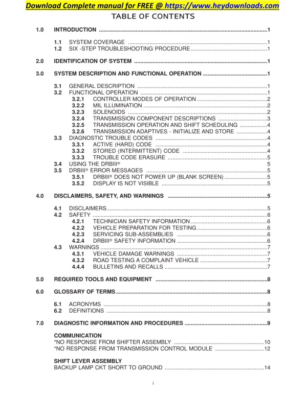
Download Complete manual for FREE @ https://www.heydownloads.com TABLE OF CONT ENT S 1.0 INTRODUCTION ..............................................................................................................1 SYSTEM COVERAGE ...........................................................................................1 SIX -STEP TROUBLESHOOTING PROCEDURE..................................................1 1.1 1.2 2.0 IDENTIFICATION OF SYSTEM .......................................................................................1 3.0 SYSTEM DESCRIPTION AND FUNCTIONAL OPERATION ..........................................1 GENERAL DESCRIPTION .....................................................................................1 FUNCTIONAL OPERATION ...................................................................................1 3.2.1 CONTROLLER MODES OF OPERATION..............................................2 3.2.2 MIL ILLUMINATION .................................................................................2 3.2.3 SOLENOIDS ...........................................................................................2 3.2.4 TRANSMISSION COMPONENT DESCRIPTIONS ................................3 3.2.5 TRANSMISSION OPERATION AND SHIFT SCHEDULING ..................4 3.2.6 TRANSMISSION ADAPTIVES - INITIALIZE AND STORE ....................4 DIAGNOSTIC TROUBLE CODES .........................................................................4 3.3.1 ACTIVE (HARD) CODE .........................................................................4 3.3.2 STORED (INTERMITTENT) CODE .......................................................4 3.3.3 TROUBLE CODE ERASURE .................................................................5 USING THE DRBIIIT ? ? ? ? ? ? ? ? ? ? ? ? ? ? ? ? ? ? ? ? ? ? ? ? ? ? ? ? ? 5 DRBIIIT ERROR MESSAGES ...............................................................................5 3.5.1 DRBIIIT DOES NOT POWER UP (BLANK SCREEN)............................5 3.5.2 DISPLAY IS NOT VISIBLE .....................................................................5 3.1 3.2 3.3 3.4 3.5 4.0 DISCLAIMERS, SAFETY, AND WARNINGS .................................................................5 DISCLAIMERS.........................................................................................................5 SAFETY ..................................................................................................................6 4.2.1 TECHNICIAN SAFETY INFORMATION..................................................6 4.2.2 VEHICLE PREPARATION FOR TESTING..............................................6 4.2.3 SERVICING SUB-ASSEMBLIES ...........................................................6 4.2.4 DRBIIIT SAFETY INFORMATION ...........................................................6 WARNINGS .............................................................................................................7 4.3.1 VEHICLE DAMAGE WARNINGS ...........................................................7 4.3.2 ROAD TESTING A COMPLAINT VEHICLE ............................................7 4.4.4 BULLETINS AND RECALLS ...................................................................7 4.1 4.2 4.3 5.0 REQUIRED TOOLS AND EQUIPMENT .........................................................................8 6.0 GLOSSARY OF TERMS...................................................................................................8 ACRONYMS ...........................................................................................................8 DEFINITIONS .........................................................................................................8 6.1 6.2 7.0 DIAGNOSTIC INFORMATION AND PROCEDURES ......................................................9 COMMUNICATION *NO RESPONSE FROM SHIFTER ASSEMBLY ...........................................................10 *NO RESPONSE FROM TRANSMISSION CONTROL MODULE ................................12 SHIFT LEVER ASSEMBLY BACKUP LAMP CKT SHORT TO GROUND .................................................................14 i
TABLE OF CONT ENT S - Continued BACKUP LAMP CKT SHORT TO VOLTAGE OR OPEN . . . . . . . . . . . . . . . . . . . . . . . .15 BACKUP LAMP SUPPLY CIRCUIT OPEN . . . . . . . . . . . . . . . . . . . . . . . . . . . . . . . . . . .16 CAN BUS CIRCUIT. . . . . . . . . . . . . . . . . . . . . . . . . . . . . . . . . . . . . . . . . . . . . . . . . . . . . .17 INCORRECT CAN MESSAGE FROM ABS. . . . . . . . . . . . . . . . . . . . . . . . . . . . . . . . . . .18 INTERNAL CONTROLLER. . . . . . . . . . . . . . . . . . . . . . . . . . . . . . . . . . . . . . . . . . . . . . . .19 LR WHEEL SPIN CAN MESSAGE NOT VALID . . . . . . . . . . . . . . . . . . . . . . . . . . . . . . .20 OVER VOLTAGE. . . . . . . . . . . . . . . . . . . . . . . . . . . . . . . . . . . . . . . . . . . . . . . . . . . . . . . .21 RR WHEEL SPIN CAN MESSAGE NOT VALID . . . . . . . . . . . . . . . . . . . . . . . . . . . . . . .22 UNDER VOLTAGE . . . . . . . . . . . . . . . . . . . . . . . . . . . . . . . . . . . . . . . . . . . . . . . . . . . . . .23 TRANSMISSION - NAG1 1-2/4-5 SOLENOID CIRCUIT . . . . . . . . . . . . . . . . . . . . . . . . . . . . . . . . . . . . . . . . . . . . . .24 1-2/4-5 SOLENOID CIRCUIT SHORT TO GROUND . . . . . . . . . . . . . . . . . . . . . . . . . . .24 2-3 SOLENOID CIRCUIT . . . . . . . . . . . . . . . . . . . . . . . . . . . . . . . . . . . . . . . . . . . . . . . . .27 2-3 SOLENOID CIRCUIT SHORT TO GROUND . . . . . . . . . . . . . . . . . . . . . . . . . . . . . .27 3-4 SOLENOID CIRCUIT . . . . . . . . . . . . . . . . . . . . . . . . . . . . . . . . . . . . . . . . . . . . . . . . .30 3-4 SOLENOID CIRCUIT SHORT TO GROUND . . . . . . . . . . . . . . . . . . . . . . . . . . . . . .30 ABS BRAKE MESSAGE. . . . . . . . . . . . . . . . . . . . . . . . . . . . . . . . . . . . . . . . . . . . . . . . . .33 ABS CAN MESSAGE INCORRECT. . . . . . . . . . . . . . . . . . . . . . . . . . . . . . . . . . . . . . . . .35 ABS CAN MESSAGE MISSING. . . . . . . . . . . . . . . . . . . . . . . . . . . . . . . . . . . . . . . . . . . .36 ABS LF SENSOR MESSAGE. . . . . . . . . . . . . . . . . . . . . . . . . . . . . . . . . . . . . . . . . . . . . .38 ABS LR SENSOR MESSAGE . . . . . . . . . . . . . . . . . . . . . . . . . . . . . . . . . . . . . . . . . . . . .40 ABS RF SENSOR MESSAGE . . . . . . . . . . . . . . . . . . . . . . . . . . . . . . . . . . . . . . . . . . . . .42 ABS RR SENSOR MESSAGE . . . . . . . . . . . . . . . . . . . . . . . . . . . . . . . . . . . . . . . . . . . . .44 ACCEL PEDAL SENSOR CAN MESSAGE INCORRECT . . . . . . . . . . . . . . . . . . . . . . .46 CAN BUS CIRCUIT. . . . . . . . . . . . . . . . . . . . . . . . . . . . . . . . . . . . . . . . . . . . . . . . . . . . . .48 CAN MESSAGE FROM ECM FROM SLA. . . . . . . . . . . . . . . . . . . . . . . . . . . . . . . . . . . .53 CONTROL MODULE TCM IS NOT CODED . . . . . . . . . . . . . . . . . . . . . . . . . . . . . . . . . .55 ENGINE CAN MESSAGE INCORRECT . . . . . . . . . . . . . . . . . . . . . . . . . . . . . . . . . . . . .56 ENGINE CAN MESSAGE MISSING . . . . . . . . . . . . . . . . . . . . . . . . . . . . . . . . . . . . . . . .58 ENGINE OVERSPEED . . . . . . . . . . . . . . . . . . . . . . . . . . . . . . . . . . . . . . . . . . . . . . . . . . .60 ENGINE RPM MESSAGE. . . . . . . . . . . . . . . . . . . . . . . . . . . . . . . . . . . . . . . . . . . . . . . . .62 ENGINE TEMP MESSAGE. . . . . . . . . . . . . . . . . . . . . . . . . . . . . . . . . . . . . . . . . . . . . . . .64 ENGINE TORQUE MESSAGE INCORRECT . . . . . . . . . . . . . . . . . . . . . . . . . . . . . . . . .66 ENGINE TORQUE REDUCTION . . . . . . . . . . . . . . . . . . . . . . . . . . . . . . . . . . . . . . . . . . .68 IC CAN MESSAGE INCORRECT . . . . . . . . . . . . . . . . . . . . . . . . . . . . . . . . . . . . . . . . . .70 IC/ATC CAN MESSAGE MISSING. . . . . . . . . . . . . . . . . . . . . . . . . . . . . . . . . . . . . . . . . .72 IMPROPER GEAR . . . . . . . . . . . . . . . . . . . . . . . . . . . . . . . . . . . . . . . . . . . . . . . . . . . . . .74 IMPROPER RATIO . . . . . . . . . . . . . . . . . . . . . . . . . . . . . . . . . . . . . . . . . . . . . . . . . . . . . .76 INPUT SENSOR MISMATCH . . . . . . . . . . . . . . . . . . . . . . . . . . . . . . . . . . . . . . . . . . . . . .78 INPUT SENSOR OVERSPEED . . . . . . . . . . . . . . . . . . . . . . . . . . . . . . . . . . . . . . . . . . . .80 INTERNAL CONTROLLER. . . . . . . . . . . . . . . . . . . . . . . . . . . . . . . . . . . . . . . . . . . . . . . .82 INVALID CONTROL MODULE VERSION . . . . . . . . . . . . . . . . . . . . . . . . . . . . . . . . . . . .83 MODULATING PRESSURE SOLENOID CIRCUIT . . . . . . . . . . . . . . . . . . . . . . . . . . . . .84 N2 INPUT SPEED SENSOR CIRCUIT . . . . . . . . . . . . . . . . . . . . . . . . . . . . . . . . . . . . . .87 N3 INPUT SPEED SENSOR CIRCUIT . . . . . . . . . . . . . . . . . . . . . . . . . . . . . . . . . . . . . .91 SENSOR SUPPLY VOLTAGE. . . . . . . . . . . . . . . . . . . . . . . . . . . . . . . . . . . . . . . . . . . . . .95 SHIFT LEVER POSITION INVALID . . . . . . . . . . . . . . . . . . . . . . . . . . . . . . . . . . . . . . . . .97 SHIFT PRESSURE SOLENOID CIRCUIT . . . . . . . . . . . . . . . . . . . . . . . . . . . . . . . . . . . .99 SLA CAN MESSAGE INCORRECT . . . . . . . . . . . . . . . . . . . . . . . . . . . . . . . . . . . . . . . .102 SOLENOID SUPPLY VOLTAGE. . . . . . . . . . . . . . . . . . . . . . . . . . . . . . . . . . . . . . . . . . .103 SOLENOID SUPPLY/WATCHDOG. . . . . . . . . . . . . . . . . . . . . . . . . . . . . . . . . . . . . . . . .105 SYSTEM OVERVOLTAGE . . . . . . . . . . . . . . . . . . . . . . . . . . . . . . . . . . . . . . . . . . . . . . .107 ii
Download Complete manual for FREE @ https://www.heydownloads.com TABLE OF CONT ENT S - Continued SYSTEM UNDERVOLTAGE .........................................................................................109 TCC OVER TEMP .........................................................................................................111 TCC SOLENOID CIRCUIT ...........................................................................................112 TCC STUCK ON ...........................................................................................................115 TRANS TEMP SENSOR - P/N SWITCH CIRCUIT ......................................................117 TRANS TEMP SENSOR ERRATIC .............................................................................120 TRANS TEMP SENSOR SHORTED ...........................................................................122 TRANSMISSION SLIPPING .........................................................................................125 VERIFICATION TESTS VERIFICATION TESTS.................................................................................................127 8.0 COMPONENT LOCATIONS .........................................................................................129 ENGINE CONTROL MODULE ...........................................................................129 TRANSMISSION CONTROL MODULE .............................................................129 TRANSMISSION SOLENOID ASSEMBLY .........................................................129 8.1 8.2 8.3 9.0 CONNECTOR PINOUTS .............................................................................................131 ELECTROHYDRAULIC CONTROL UNIT - BLACK ....................................................131 SHIFTER ASSEMBLY - BLACK ...................................................................................131 TRANSMISSION CONTROL MODULE C1 - BLACK ..................................................131 TRANSMISSION CONTROL MODULE C2 - BLACK ..................................................132 TRANSMISSION RELAY (RELAY BLOCK) .................................................................133 10.0 SCHEMATIC DIAGRAMS.............................................................................................135 11.0 CHARTS AND GRAPHS .............................................................................................137 11.1 5 VOLT SQUARE WAVE – TYPICAL PATTERN ................................................137 11.2 TRANSMISSION TEMP SENSOR .....................................................................138 iii
NOTES iv
Download Complete manual for FREE @ https://www.heydownloads.com GENERAL INFORMAT ION 1.0 INT RODUCT ION tronic transmission is a conventional transmission in that it uses hydraulically applied clutches toshift a planetary gear train. However, the electronic control system replaces many of themechanical and hydraulic components used in conventional trans- mission valve bodies. The ratios for the gear stages are obtained by 3 planetary gear sets. Fifth Gear is designed as an Overdrive with a high speed ratio. The gears are actuated electronically/hydraulically. Theelectronic control system enables precise adaptation of pres- sures to the respective operating conditions and to the engine output during a shift phase, which results in a significant improvement in shift qual- ity. The procedures contained in this manual include all of the specifications, instructions, and graphics needed to diagnose NAG1 Electronic Automatic Transmission and Shift Lever Assembly problems. The diagnostics in this manual are based on the failure condition or symptom being present at the time of diagnosis. When repairs are required, refer to the appropri- ate volume of the service information for the proper removal and repair procedure. R E AD T HIS MANUAL BE F OR E T RYING T O DIAGNOSE A VE HICL E T R OUBL E CODE . Diagnostic procedures change every year. New diagnostic systems may be added and/or carryover systems may be enhanced. It is recommended that you review the entire manual to become familiar with all new and changed diagnostic procedures. 3.2 FUNCTIONAL OPERATION The NAG1 electronic transmission has a fully adaptive control system. The system performs its functions based on continuous real-time sensor and switch feedback information. In addition the TCM receives information from theShift Lever Assembly, ECM (engine management) and ABS (chassis sys- tems) controllers over theCAN bus. TheCAN bus is a high speed communication bus that allows real time control capability between various controllers. Most messages are sent every 20 milliseconds, this means critical information can be shared between the Transmission, Shifter, Engine and ABS control- lers. The CAN bus is a two wire bus with a CAN C Bus (+) circuit and a CAN C Bus (-) circuit. The CAN bus uses a twisted pair of wires in the harness to reduce the potential of radio and noise interfer- ence. TheCAN bus alsouses a 120 ohm terminating resistor in both the ECM and Sentry Key Remote Entry Module (SKREEM) modules. The module terminating resistance is measured across both CAN bus circuits at the ECM or SKREEM module. The control system automatically adapts to changes in engine performance, vehicle speed, and transmission temperature variations to provide consistent shift quality. The control system ensures that clutch operation during upshifting and down- shifting is more responsive without increased harshness. The TCM controls the actuation of sole- noid valves for modulating shift pressure and gear change. The required pressure level is calculated from the load condition, engine speed. Power for the transmission system is supplied through the Trans- mission Relay. The TCM is located in the under the drivers seat of the vehicle. The Transmission Control Module (TCM) contin- uously checks for electrical problems, mechanical problems, and some hydraulic problems. When a problem is sensed, the TCM stores a diagnostic trouble code (DTC). Some of these codes cause the transmission to go into 9limp-in9 or 9default9 mode. 1.1 SYSTEM COVERAGE This diagnostic procedures manual covers all Sprinter (VA) equipped with a NAG1 Automatic Transmission. 1.2 SIX -STEP TROUBLESHOOTING PROCEDURE Diagnosis of the NAG1 electronic transmission is done in six basic steps: Verification of complaint Verification of any related symptoms Symptom analysis Problem isolation Repair of isolated problem Verification of proper operation 2.0 IDENT IFICAT ION OF S Y S T EM The NAG1 Transmission family can be identified by thepresenceof a 13 pin electrical connector, with a bayonet lock on the right hand side of the trans- mission. The connector is oriented horizontally. 3.0 S Y S T EM DES CRIPT ION AND FUNCT IONAL OPERAT ION 3.1 GENERAL DESCRIPTION The NAG1 electronic transmission is an electron- ically controlled five speed transmission with a controlled slip torque converter. The NAG1 elec- 1
GENERAL INFORMAT ION The NAG1 will default in the current gear position if a DTC is detected, then after a key cycle or shift topark thetransmission will gointoLimp-in, which is mechanical 2nd gear. Some DTC’s may allow the transmission to resume normal operation (recover) if the detected problem goes away. Permanent limp-in DTC will recover when thekey is cycled, but if the same DTC is detected for three key cycles the system will not recover and the DTC must be cleared from the TCM with the DRBIII scan tool. Once the DRBIIIt is in the Transmission portion of the diagnostic program, it constantly monitors the TCM to see if the system is in limp-in mode. If the transmission is in limp-in mode, the DRBIIIt will flash the red LED. Improper Ratio, Input Sensor Overspeed, or Engine Overspeed DTC’s will cause the loss of drive. Controlled L imp-in Mode When a failure condition does not require the TCM to shut down the solenoid supply, but the failure is of a degree where the TCM will place the transmis- sion into a predefined gear, there will be several shift performance issues. Examples of this are, with the transmission slipping the controller will at- tempt to place the transmission into third gear and maintain third gear for all forward driveconditions. Another example is some of the CAN bus message issues if the TCM does not receive required infor- mation from the Engine Controller, then default values are used which may result in poor transmis- sion shift performance. CONTROLLER MODES OF OPERATION Permanent limp-in mode When the TCM recoverable condition present that will not allow proper transmission operation, it will place the transmission in permanent limp-in mode. When the condition occurs the TCM will turn off all solenoids as well as the solenoid supply output circuit. If this occurs whilethevehicleis moving, thetransmission will remain in the current gear until the ignition is turned off or shifter is placed in the 9P9 position. Once the shifter has been placed in 9P9 the Trans- mission will only allow 2nd gear operation. If the problem occurs while the vehicle is not moving the transmission will only allow 2nd gear operation. 3.2.1 3.2.2 For failures detected by the Transmission Con- troller that result in the controller placing the transmission intoa limp-in mode, except for System Overvoltage and System Undervoltage DTCs, the MIL will be illuminated. The Transmission Control Module will inform the ECM over the CAN bus that a failure has occurred. The ECM will illuminate the MIL. If the condition is removed and the failure becomes Stored (Intermittent), the Transmission controller will stop reporting that the DTC is active and the ECM will extinguish the MIL. MIL ILLUMINATION determines there is a non- NOTE: The MIL will light when the problem is first detected and it will not go off until the next ignition cycle, conditions have been checked for their presence. This normally minutes of driving. after all problem Temporary limp-in mode This mode is the same as the permanent limp-in modeexcept if thecondition is nolonger present the system will resume normal operation. (Recoverable DTC) takes several 3.2.3 1-2/4-5 solenoid - The 1-2/4-5 solenoid is activated when the TCM determines that the transmission must shift into or out of 2nd gear or 5th gear. The solenoid is only activated during the shifting of the transmission. When the solenoid is activated, hy- draulic pressure is applied to the proper shift ele- ments in thetransmission toallow thedesired shift. Once the shift is completed, the solenoid is turned off. SOLENOIDS Undervoltage limp-in mode When the TCM detects that system voltage has dropped below 8.5 volts it will disable voltage de- pendant diagnostics and place the transmission in the temporary limp-in mode. When the TCM senses that the voltage has risen above 9.0 volts, normal transmission operation will be resumed. Hardware E rror Mode When the TCM detects a major internal error the transmission will be placed in the permanent limp-in mode and cease all communication over the CAN bus. Once the TCM has entered this mode normal transmission operation will not resume un- til all DTC’s are cleared from the TCM. 2-3 solenoid - The 2-3 solenoid is activated when the TCM determines that the transmission must shift into or out of 3rd gear. The solenoid is only activated during the shifting of the transmission. When the solenoid is activated hydraulic pressure is applied to the proper shift elements in the trans- mission to allow the desired shift. Once the shift is completed, the solenoid is turned off. L oss of Drive If the TCM detects a situation that has resulted or may result in engine or transmission failure, the transmission will be placed in the neutral position. 2
Download Complete manual for FREE @ https://www.heydownloads.com GENERAL INFORMAT ION (4MPH). The Reverse inhibitor is part of the Shift Lever Assembly and is controlled by the Shift Lever Assembly module. 3-4 solenoid - The 3-4 solenoid is activated when the TCM determines that the transmission must shift into or out of 4th gear. The solenoid is only activated during the shifting of the transmission. When the solenoid is activated, hydraulic pressure is applied to the proper shift elements in the trans- mission to allow the desired shift. Once the shift is completed, the solenoid is turned off. Trans temp sensor - P/N Switch circuit The TCM will detect the selector lever in park and neutral positions. The TCM does this by monitoring the Transmission temperature sensor signal along with the shifter position signals. The P/N switch contact is operated by a cam located in the trans- mission which, opens a reed contact switch that is wired in series with the transmission temperature sensor. When the P/N contact switch is opened in park and neutral, the TCM senses a high transmis- sion temperature. Confirming the P/N switch sta- tus. Note: In park or neutral, the TCM uses engine temperature (to avoid setting a DTC). The TCM sends a hardwired signal totheECM that will allow the ECM controlled start circuit toengage in P or N only. The TCM also sends a P/N bus message to the ECM to confirm the P/N switch status. T CC solenoid - The TCC solenoid is activated when the TCM determines that the Torque con- verter clutch should be activated. The TCC clutch is a variable slip torque clutch that allows control of torque converter slip from 5% to 95.5% of full TCC engagement. The clutch is controlled by the TCC solenoid which is pulse width modulated (PWM) to provide the desired amount of slip. Shift Pressure Solenoid - The Shift Pressure Solenoid is activated when the TCM determines that a transmission shift is required. The solenoid is PWM controller to allow the proper amount of hydraulic pressure to the shift elements. The sole- noid is only activated during the shifting of the transmission. When the solenoid is activated, hy- draulic pressure is removed from the proper shift elements toallow the desired shift. Once the shift is completed, the solenoid is turned off. The Normal Transmission Temperature Sensor resistance is between 500.0 and 2500.0 ohms. T he normal voltage limits for the transmis- sion temperature sensor, are between 0.5 and 3.0 volts. Input Speed Sensors The NAG1 transmission has two input speed sen- sors N2 and N3, both speed sensors are located on the valve body and report DTC’s for the input speed sensors errors. The speed sensors are Hall Effect speed sensors that areused by theTCM tocalculate the transmissions input speed. Since the input speed could not be measured directly, two of the drive elements are measured. Two input speed sensors were required because both drive elements arenot activein all gears. Theinput sensors N2 and N3 will report the same input speed in gears 2nd, 3rd or 4th. If the N2 and N3 input speed signals are not the same in these gears then there is an issue with the transmission and the DTC Input Sensors Mismatch will be set. The N3 input speed is not reported in1st and 5th gears. The N2 sensor is not reported in Reverse. The Input Speed Sensor Overspeed is a rationality check that is intended toindicate a major transmis- sion failure and will cause a loss of drive (place the transmission in Neutral) Modulation pressure solenoid - The modulation pressure is always active. The solenoid is pulse width modulated (PWM) controlled and is used to modulate the hydraulic system pressure to the desired pressure. TRANSMISSION COMPONENT DESCRIPTIONS Shift Assembly The Shift Lever Selector transmits all selector lever positions, as well as selected shift ranges to the TCM over the CAN Bus. At the same time, the selector lever positions P, R, N, and D are transmit- ted by a cable to the selector lever shaft in the transmission. 3.2.4 Brake shift inter-lock To prevent unauthorized shifting out of the park position, the Selector lever is locked in the Park position until the ignition key is turned to the run position and the brake pedal is pressed. This will allow the driver to shift out of the park position. Output Speed Sensor (ABS signal) The NAG1 transmission does not have an output shaft speed sensor. The TCM uses the ABS (An- tilock Brake System) Wheel Speed sensor informa- tion, it receives over the CAN bus, to calculate the transmissions output shaft speed. The TCM moni- tors the ABS system for functionality and reports ABS speed sensor and communication DTCs, which will affect proper transmission operation. R everse L amp Output The Reverse Light Switch is integrated into the shifter module and controls the reverse lights. R everse Inhibitor The Shift Lever Assembly constantly monitors ABS wheel speed to prevents an inadvertent selection of reverse at speeds above approximately 6.4 Km/h 3
GENERAL INFORMAT ION 3.2.5 TRANSMISSION OPERATION AND SHIFT SCHEDULING The transmission covered in this manual has unique shift schedules depending on the tempera- ture of the transmission oil. The transmission oil temperature has a decisive effect on the shift qual- ity of the transmission. The shift schedule is modi- fied to extend the life of the transmission while operating under extreme conditions and to improve driver comfort by modifying shift schedules. The transmission oil temperature is measured with a Temperature Sensor on the NAG1 transmis- sion. The Temperature Sensor is an integral com- ponent of the Transmission Solenoid assembly. If the Temperature Sensor is causing a problem, a DTC will be set in the TCM. The Transmission Temperature Sensor is wired in series with the Park /Neutral (P/N) switch. The P/N switch is also located in the transmission. The trans- mission temperature is only read by the TCM when the P/N switch closes while in the R, D position. When the shifter lever is in the park or neutral position, the P/N switch opens and the temperature being displayed is Engine temperature. lems can be misinterpreted as a transmission prob- lem. Ensure that the engine is running properly and that no ECM DTC’s are present that could cause a transmission complaint. If there is a communication K-ABS,Shifter or K-TCM circuit problem, trouble codes will not be accessible until the problem is fixed. The DRBIIIt will display an appropriate message. The following is a possible list of causes for a bus problem: – open or short to ground/battery in K line circuit. – internal failure of any module or component connected to the K line circuit Each diagnostic trouble code is diagnosed by following a specific testing sequence. Thediagnostic test procedures contain step-by-step instructions for determining the cause of a transmission diag- nostic trouble code. Possible sources of the code are checked and eliminated one by one. It is not neces- sary to perform all of the tests in this book to diagnose an individual code. These tests are based on the problem being present at the time that the test is run. If the TCM records a DTC that will adversely affect the vehicles transmission, it will request (via the communication bus) that the ECM illuminate the Malfunction Indicator Lamp (MIL). All trans- mission DTC’s will be stored in the TCM. AutoStick F eature (If equipped) This feature allows the driver tomanually shift the transaxle when the shift lever is moved sideways to the (+ / -) in position D to adjust the shift range. 3.3.1 Any Diagnostic Trouble Code (DTC) that is set whenever the system or component is monitored is an Active code. This means that the problem is there every time the TCM checks that system or component. Some codes will set immediately at start up and others will require a road test under specific conditions to set the DTC. It must be determined if a code is Active (repeatable) or Stored (Intermittent) before attempting diagnosis. ACTIVE (HARD) CODE 3.2.6 TRANSMISSION ADAPTIVES - INITIALIZE AND STORE Initialize Adaptive - This TCM function should be used when a new transmission has been placed in the vehicle. This command will reset the TCM adaptive to the factory setting. Store Adaptive - This command should be used after the vehicle has been test driven by the tech- nician to store any learned adaptive changes that occurred during the test drive. During normal op- eration adaptive are updated every 10 minutes. Using this command the latest adaptive will be written to the TCM immediately. 3.3.2 A diagnostic trouble code that is not there every time the TCM checks the circuit or function is a Stored (Intermittent) code. Problems that come and go like this are the most difficult to diagnose, they must be looked for under the specific conditions that cause them. If the DTC is reset (after an ignition cycle) the DTC will be set to Stored (Inter- mittent) status. A DTC status can be 9Active9 or 9Stored9 (Intermittent). Active is when the DTC is present in the controller and the transmission is in the particular mode of operation for that DTC. Stored means that the DTC occurred at some point, but is not currently present, or the conditions have not been right to check for the presence of the problem, when a DTC is classified as Stored (Inter- mittent), no TCM reaction is required. STORED (INTERMITTENT) CODE 3.3 DIAGNOSTIC TROUBLE CODES Diagnostic trouble codes (DTC’s) are codes stored by the Transmission Control Module (TCM) and the Shift Lever Assembly Module (SLA) to help diag- nose Transmission and Shifter problems. They are viewed using the DRBIIIt scan tool. Always begin by performing a visual inspection of the wiring, connectors, cooler lines and the trans- mission. Any obvious wiring problems or leaks should be repaired prior toperforming any diagnos- tic test procedures. Some engine driveability prob- 4
Download Complete manual for FREE @ https://www.heydownloads.com GENERAL INFORMAT ION E mergency running function If DTCs occur, safe-driving conditions must be re- tained but full functionality of thetransmission will be limited to avoid damaging the automatic trans- mission. In the event of certain DTCs the TCM switches toemergency running. The TCM will store the appropriate DTC codes and solenoids will be de-energized (turned off) The transmission effects will be: • The last gear shifted remains in that position • The modulating pressure and shift pressure in- crease to maximum value • The (turned off) torque converter clutch is disengaged Shifting manually after a DT C detection 3.5 DRBIIIT ERROR MESSAGES NOTE: The vehicle can still be shifted manually to 2nd or reverse gear. Under normal operation, the DRBIIIt will display one of only two error messages: – User-Requested WARM Boot – User-Requested COLD Boot If the DRBIIIt should display any other error message, record the entire display and call the S.T.A.R. Center. To accomplish these shifts you must Stop the vehicle Turn the ignition off Start the engine Place the selector lever into D for 2nd gear Place the selector lever into R for reverse gear The emergency running function is retained until the DTC is eliminated or the stored DTC code is erased. Stored (Intermittent) DTCs can be reset by cy- cling the ignition switch 3.5.1 DRBIIIT DOES NOT POWER UP (BLANK SCREEN) If the LED’s donot light or nosound is emitted at start up, check for loose cable connections or a bad cable. Check the vehicle battery voltage. A mini- mum of 11 volts is required toadequately power the DRBIIIt. If all connections are proper between the DRBI- IIt and the vehicle or other devices, and the vehicle battery is fully charged, an inoperative DRBIIIt may be the result of faulty cable or vehicle wiring. For a blank screen, refer to the appropriate Body Diagnostic manual. 3.3.3 Diagnostic Trouble Codes can be erased in two ways. The first is toerase the DTC with the DRBIII or scan tool. The second is if the DTC is no longer present, the DTC is reset by the TCM (after an ignition cycle), which will place the DTC in an intermittent status (Stored DTC). TROUBLE CODE ERASURE When there are no diagnostic trouble codes stored in memory, the DR BIIIt will display (NO DT C’s DE T E CT E D( 3.5.2 Low temperatures will affect the visibility of the display. Adjust the contrast to compensate for this condition. DISPLAY IS NOT VISIBLE 3.4 USING THE DRBIIIT Refer tothe DRBIIIt user’s guide for instructions and assistance with reading trouble codes, erasing trouble codes, and other DRBIIIt functions. 4.0 DIS CLAIMERS , S AFET Y, AND WARNINGS 4.1 DISCLAIMERS All information, illustrations, and specifications contained in this manual are based on the latest 5
GENERAL INFORMAT ION information available at the time of publication. The right is reserved to make changes at any time without notice. improper system operation. Only those components with approved repair and installation procedures in the service information should be serviced. 4.2 SAFETY 4.2.4 DRBIIIT SAFETY INFORMATION WARNING: EXCEEDING THE LIMITS OF THE DRBIIIT MULTIMETER IS DANGEROUS. IT CAN EXPOSE YOU POSSIBLY FATAL INJURY. READ AND UNDERSTAND THE CAUTIONS AND THE SPECIFICATION LIMITS. 4.2.1 TECHNICIAN SAFETY INFORMATION TO SERIOUS CAREFULLY OR WARNING: ENGINES PRODUCE CARBON MONOXIDE THAT IS ODORLESS, CAUSES SLOWER REACTION TIME, AND CAN LEAD TO SERIOUS INJURY. WHEN THE ENGINE IS OPERATING KEEP SERVICE AREAS WELL VENTILATED OR ATTACH THE VEHICLE EXHAUST SYSTEM TO THE SHOP EXHAUST REMOVAL SYSTEM. Set theparking brakeand block thewheels before testing or repairing the vehicle. If is especially important to block the wheels on front-wheel drive vehicles: the parking brake does not hold the drive wheels. Some operations in this manual require that hydraulic tubes, hoses, and fittings, disconnected for inspection or testing purposes. These systems, when fully charged, contain fluid at high pressure. Before disconnecting any hydraulic tubes, hoses, and fittings, be sure that the system is fully depres- surized. When servicing a vehicle, always wear eye pro- tection, and remove any metal jewelry such as watchbands or bracelets that might make an inad- vertent electrical contact. When diagnosing a Transmission system prob- lem, it is important to follow approved procedures where applicable. These procedures can be found in the service information. Following these procedures is very important to the safety of individuals per- forming diagnostic tests. • Follow the vehicle manufacturer’s service speci- fications at all times. • Do not use the DRBIIIt if it has been damaged. • Do not use the test leads if the insulation is damaged or if metal is exposed. • To avoid electrical shock, do not touch the test leads, tips or the circuit being tested. • Choose the proper range and function for the measurement. Donot try voltage or current mea- surements that may exceed the rated capacity. • Do not exceed the limits shown in the table. F UNCT ION INPUT L IMIT Volts 0-500 volts peak AC 0-500 volts DC Ohms (resistance)* 0-1.12 megohms Frequency measured Frequency generated 0-10 khz Temperature -58-1100°F -50-600C *Ohms cannot be measured if voltage is present. Ohms can be measured only in a non-powered circuit. 4.2.2 VEHICLE PREPARATION FOR TESTING Make sure the vehicle being tested has a fully charged battery. If it does not, false diagnostic DTC’s or error messages may occur. It is extremely important that accurate shift lever position data is available to the TCM. The accuracy of any DTC found in memory is doubtful unless the Shift Lever Test, performed on the DRBIIIt Scan Tool, passes without failure. • Voltage between any terminal and ground must not exceed 500v DC or 500v peak AC. • Use caution when measured voltage above 25v DC or 25v AC. • The circuit being tested must be protected by a 10A fuse or circuit breaker. • Use the low current shunt tomeasure circuits up to 10A. Use the high current clamp to measure circuits exceeding 10A. • When testing for the presence of voltage or cur- rent, make sure the meter is functioning cor- rectly. Take a reading of a known voltage or current before accepting a zero reading. • When measuring current, connect the meter in series with the load. 4.2.3 Somecomponents of theTransmission system are intended to be serviced in assembly only. Attempt- ing to remove or repair certain system sub- components may result in personal injury and/or SERVICING SUB-ASSEMBLIES 6
Download Complete manual for FREE @ https://www.heydownloads.com GENERAL INFORMAT ION and condition before taking the vehicle on a road test. Determine if the incorrect fluid is being used, improper fluid will result in erratic transmission operation. • Disconnect the live test lead before disconnecting the common test lead. • When DRBIIIt away from spark plug or coil wires to avoid measuring error from outside interference. using the meter function, keep the Some of the conditions of incorrect fluid level are as follows: • Delayed engagement • Poor shifting or erratic shifting • Excessive noise • Overheating The next step is to verify that the shift linkage is correctly adjusted. If the shift linkage is incorrectly adjusted, a number of complaints can result. The TCM monitors the Shift Lever Position (SLP) continuously. If the linkage is incorrectly adjusted, the TCM will sense a shift lever position that is not correct for the gear chosen by the driver. This may cause a DTC to be set. 4.3 WARNINGS 4.3.1 Before disconnecting any control module, make sure the ignition is 9lock9 position. Failure to do so could damage the module. When testing voltage or continuity at any control module, use the terminal side (not the wire end) of the connector. Do not probe a wire through the insulation: this will damage the wire and eventu- ally cause the wire to fail because of corrosion. Be careful when performing electrical tests so as to prevent accidental shorting of terminals. Such mistakes can damage fuses or components. Also, a second DTC could be set, making diagnosis of the original problem more difficult. When replacing a blown fuse, it is important to use only a fuse having the correct amperage rating. The use of a fuse with a rating other than indicated may result in a dangerous electrical system over- load. If a properly rated fuse continues to blow, it indicates a problem in the circuit that must be corrected. VEHICLE DAMAGE WARNINGS The following complaints may also be the result of an incorrectly adjusted or worn linkage: • Delayed clutch engagement • Erratic shifts • Vehicle will drive in neutral • Engine will not crank in park or neutral • Gear shift linkage will be able to be shifted without the key in the ignition • Not able to remove the ignition key in park • Parking pawl will not engage properly The shift linkage should also be adjusted when replacing the Transmission, repairing the valve body, or when repairing any component between the shift lever and the Transmission. 4.3.2 ROAD TESTING A COMPLAINT VEHICLE Some complaints will require a test drive as part of the repair verification procedure. The purpose of the test drive is to try to duplicate the diagnostic DTC or symptom condition. Some questions to ask yourself when performing the road test are as follows: • Is the complaint or concern what you think the problem is, based on thedrivers description of the problem? • Is the Transmission operating normally, or is there a real problem? • When does the problem occur? • Is the problem only in one gear range? • What temperature does the problem occur? • Does the vehicle have to sit over night for the problem to occur? • Does the transmission go into Limp-in mode? 4.4.4 BULLETINS AND RECALLS Always perform all Safety Recalls and Technical Service Bulletins that are applicable to the prob- lem. CAUTION: Before road testing a vehicle, be sure that all components are reassembled. During the test drive, do not try to read DRBIIIT screen while in motion. Do not hang the DRBIIIT from the rear view mirror or operate it yourself. available to operate the DRBIIIT. Have an assistant Road testing is an essential step in the diagnostic process that must not be overlooked. Along with the diagnostic information obtained from the DRBIIIt Scan Tool and the original customer concern, the road test helps verify the problem was current and any repairs performed, fixed the vehicle correctly. Always operate and observe the vehicle under ac- tual driving conditions. J ust as important as the road test is, there are preliminary inspections that should be performed prior to the road test. Always check the fluid level 7
GENERAL INFORMAT ION 5.0 REQUIRED T OOLS AND EQUIPMENT OSS Output Speed Sensor (derived from the ABS controller) PE MCC Partial Electronically Modulated Converter Clutch > DRBIIIt (diagnostic read-out box) - DRBIIIt must use the latest release level. > J umper wires > Test Light > Ohmmeter > Voltmeter PWM Pulse width modulated SK R E E M Sentry Key Remote Entry Module SL A Shift Lever Assembly SW Switch T CC Torque Converter Clutch 6.0 GLOS S ARY OF T ERMS T CM Transmission Control Module T P Throttle Position 6.1 ACRONYMS T R D Torque Reduction ABS Antilock Braking system T T S Transmission Temperature Sensor A/C Air conditioner 1-2/4-5 solenoid controls the shift into and out of 2nd gear or 5th gear. A/D Analog to Digital conversion APP Accelerator Pedal Position V2-3 so- lenoid controls the shift into and out of 3rd gear CAN Controller Area Network (Vehicle Bus System) V3-4 so- lenoid controls the shift into and out of 4th gear CK T Circuit VT CC solenoid is pulse width modulated and con- trols the TCC clutch DL C Data Link Connector DR BIIIt Diagnostic Readout Box Shift Pressure Solenoid is a pulse width modulated solenoid and controls the hydraulic pressure to the shift elements. DT C Diagnostic Trouble Code E CM Diesel Engine Controller Modula- tion pressure solenoid is a pulse width modulated solenoid and controls the hydraulic system pressure E MCC Electronically Modulated Converter Clutch IOD Ignition off-draw 6.2 DEFINITIONS ISS Input Speed Sensor (N2 and N3) K K line communication bus Driving cycle counter) - The starts since first set counter indicates the number of driving cycles since the first occurrence of an error. L E D Light Emitting Diode MIL Malfunction Indicator Lamp 8
Download Complete manual for FREE @ https://www.heydownloads.com 7.0 DIAGNOS T IC INFORMAT ION AND PROCEDURES 9
COMMUNICAT ION Symptom: *NO R E SPONSE F R OM SHIF T E R ASSE MBLY POSSIBL E CAUSE S CHECK POWERS AND GROUNDS TO THE SHIFTER ASSEMBLY CONTROLLER ANTILOCK BRAKE K-ABS, SHIFTER ASSEMBLY CIRCUIT SHORTED TO GROUND CONTROLLER ANTILOCK BRAKE K-ABS, SHIFTER ASSEMBLY CIRCUIT SHORTED TO VOLTAGE K-ABS, SHIFTER ASSEMBLY CIRCUIT OPEN SHIFTER ASSEMBLY T E ST ACT ION APPL ICABIL IT Y 1 Turn the ignition off. Disconnect the Shifter Assembly harness connector. Check each power and ground circuit to the module. Were any problems found? All Yes Refer tothe wiring diagrams located in the service information to help isolate an open or shorted condition. Repair as necessary. Perform NAG1 TRANSMISSION VERIFICATION TEST - VER 1. → No Go To 2 → 2 Turn the ignition off. Disconnect the Shifter Assembly harness connector. Disconnect the DRBIIIt from the DLC. Measure the resistance between ground and the K-ABS, Shifter Assembly circuit. Is the resistance below 5.0 ohms? All Yes Go To 3 → → No Go To 4 3 Turn the ignition off. Disconnect the CAB harness connector. Measure the resistance between ground and the K-ABS, Shifter Assembly circuit. Is the resistance below 5.0 ohms? All Yes Repair the K-ABS, Shifter Assembly circuit for a short toground. Perform NAG1 TRANSMISSION VERIFICATION TEST - VER 1. → No Replace the Controller Antilock Brake in accordance with the service information. Perform NAG1 TRANSMISSION VERIFICATION TEST - VER 1. → 10