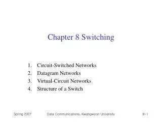
Ch 8. Switching
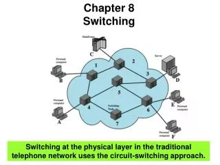
Ch 8. Switching. Switch. Devices that interconnected with each other Connecting all nodes (like mesh network) is not cost-effective Some topology like bus has limitation on distance Switched network, where end systems (e.g., A, B, … J) are connected through switches (e.g., I, II, … V).

Ch 8. Switching
E N D
Presentation Transcript
Switch • Devices that interconnected with each other • Connecting all nodes (like mesh network) is not cost-effective • Some topology like bus has limitation on distance • Switched network, where end systems (e.g., A, B, … J) are connected through switches (e.g., I, II, … V)
Taxonomy of Switched Networks Telephone system The Internet (IP)
Circuit-Switched Networks • A set of switches are connected by physical links • Each link is divided into n channels using FDM or TDM • Each connection has one dedicated channel • Example (n = 3)
Circuit Switching • Resources (channels, switch buffer, switch processing time, switch ports, etc) must be reserved before communication, and released after communication • Three phases • Setup – establish a connection and reserve the resources for communication • Data transfer – do communication • Teardown – finishing communication, release the resources
Setup Teardown
Example of Circuit-Switched Network • Three switches are used to “route” 4 connections
Properties of Circuit-Switching • Require resource reservation and release • Data do not needed to be packetized • No addressing is involved during data transfer • Low efficiency • Reserved resources are unavailable to others • Low delay • Except the setup delay for the resource reservation
Datagram Networks • Messages pass through packet-switched networks, without reserving resources • Resources are allocated on demand • Data should be divided into small pieces, called packet or datagram • Each packet is treated independently of others • Network has no idea about data stream • Often called, connectionless networks, since the switch does not keep information about the connection state
Routing • How the switches route packets without reserving resources? • Each packet carries its destination address • Each switch keep routing table, which is dynamic and updated periodically • Routing table • Specifies the output port of the switch for each destination address
Properties of Packet-Switching • Resources are allocated on demand • Data should be packetized, and each packet should include its destination address • High efficiency – more multiplexing • High delay
Recall the Taxonomy Telephone system The Internet (IP)
Virtual-Circuit Networks • Can be regarded as a blend of both a circuit-switched network and a datagram network • Three phases: setup, transfer, and teardown • Resources can be reserved at setup, or allocated on demand • Data are packetized and each packet carries an address • Normally, switches are implemented at • physical layer - Circuit-switched networks • network layer - Packet-switched networks • data link layer - Virtual-circuit networks
Addressing • Two-level addressing • Global addressing – address is unique over networks • Virtual-circuit identifier (VCI, local addressing) – used by a frame between two switches
Routing Table • Routing using (port, VCI)
Connection Setup (1) • Request (source destination) How does switch 1 know it should go to port 3? This will be covered later
Connection Setup (2) • Acknowledgement (destination source)
Properties of VC Switching • Three phases • Setup • Data transfer – all packets belonging to the same source and destination travel the same path • Teardown – the similar method as setup (i.e., request and confirm) • Efficiency and delay • Depends on whether resources are either reserved during the setup, or allocated on demand • Advantage • The source can check availability of the resources, without actually reserving it.
Structure of a Switch • Switches are used in both circuit-switched and packet-switched networks • Circuit switch • Space-division switch: paths in the circuit are separated from one another spatially • Time-division switch: internally uses time-division multiplexing (TDM) • Packet Switch
Space-Division Switch (1) • Crossbar Switch • Connect n inputs to m outputs in a grid • Switch with too many crosspointsis impractical and inefficient
Space-Division Switch (2) • Multi-stage Switch • Combine crossbar switches in several stages (usually three) • Ex: number of crosspoints? • N/n (n x k) + k (N/n x N/n) + N/n (k x n) = 2kN + k(N/n)2 • This is much smaller than single-stage crossbar: N2
Space-Division Switch (3) • Blocking – problem of multistage switch • Under heavy traffic, resources (i.e., crosspoints) are limited, if many users want a connection at the same time • Blocking refers to times when one input cannot be connected to an output due to no available path • Can we avoid blocking? • Clos criterion: n = (N/2)1/2, k > 2n-1 • Number of crosspoitns ≥ 4N ((2N)1/2 – 1) • This is still huge, though less than N2
Time-Division Switch • Time-Slot Interchange (TSI) • TDM muxer, demuxer • TSI with Random Access Memory (RAM) • To support inputs continuously, TSI should operate at a faster rate – speed-up
Time- and Space-Division Switch • Space-division requires many cross-points • Time-division requires speed-up (or delay if store in the switch) • Time-space-time (TST) switch
Packet Switches • Components: • Input port, routing processor, switching fabric, output port
Packet Switch Structure (1) • Input port performs the physical and data link functions: decapsulates packet from the frame, detects/corrects errors, and store packets at its queue • Output port performs the same function of the input port, but in the reverse order
Packet Switch Structure (2) • Routing processor performs the functions of the network layer: finds the output port number by looking up the routing table (table lookup) • Switching fabrics move packets from the input queue to the output queue • Crossbar • Banyan • Batch-Banyan
Banyan Switch • Multistage switch with many 2x2 micro-switches • log2 n stages, n/2 micro-switches at each stage • Packets are automatically routed to the destination using the binary expression of the destination address Banyan tree from dailycognition.com
Banyan Switch • Micro-switch (2x2) • A packet has a control bit, 0 or 1 • The packet goes up if the control bit is 0 • The packet goes down if the control bit is 1 0 or 1 0 0 1 0 or 1 0 1 1
Banyan Switch Control bit at 1st stage Control bit at 2nd stage • Two examples • Left figure: packet to output 6 (= 110) • Right figure: packet to output 2 (= 010) Control bit at 3rd stage
Banyan Switch • First bit determines the block of the next stage • Two blocks are separated • First bit indicates which block the packet should go • Procedure repeats at the next stage with the next bit
Batcher-Banyan Switch Collision • Collision of packets even for a different dest. • At port 0, to dest. 4 (100) • At port 6, to dest. 5 (101) • Pre-sorting can solve the problem • E.g., the second packet arrives at port 1 • Batcherswitch doesthe sorting
Homework • Exercise in Chap. 8 • 13 • 18 • 22 • 23