Current, Resistance and Electromotive Force
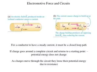
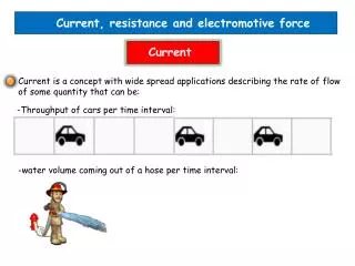
Current, Resistance and Electromotive Force. Current. A current is any motion of charge from one region to another In electrostatic situations (discussed in Chapters 21 through 24) the electric field is zero everywhere within the conductor, and there is no current

Current, Resistance and Electromotive Force
E N D
Presentation Transcript
Current • A current is any motion of charge from one region to another • In electrostatic situations (discussed in Chapters 21 through 24) the electric field is zero everywhere within the conductor, and there is no current • However, this does not mean that all charges within the conductor are at rest.
Current • In an ordinary metal such as copper or aluminum, some of the electrons are free to move within the conducting material. • These free electrons move randomly in all directions, somewhat like the molecules of a gas but with much greater speeds, of the order of 106 m/s.
Current • The electrons nonetheless do not escape from the conducting material, because they are attracted to the positive ions of the material • The motion of the electrons is random, so there is no net flow of charge in any direction and hence no current.
Current • if a constant, steady electric field E is established inside a conductor • A charged particle(such as a free electron) inside the conducting material is then subjected to a steady force F=qE
Current • If the charged particle were moving in vacuum, this steady force would cause a steady acceleration in the direction of F • and after a time the charged particle would be moving in that direction at high speed. • But a charged particle moving in a conductor undergoes frequent collisions with the massive, nearly stationary ions of the material
Current • In each such collision the particle’s direction of motion undergoes a random change • The net effect of the electric field E is that in addition to the random motion of the charged particles within the conductor, there is also a very slow net motion or drift of the moving charged particles as a group in the direction of the electric force F=qE
Current • This motion is described in terms of the drift velocity vdof the particles • As a result, there is a net current in the conductor
The Direction of Current Flow • The drift of moving charges through a conductor can be interpreted in terms of work and energy • The electric field E does work on the moving charges • The resulting kinetic energy is transferred to the material of the conductor by means of collisions with the ions, which vibrate about their equilibrium positions in the crystalline structure of the conductor.
The Direction of Current Flow • This energy transfer increases the average vibrational energy of the ions and therefore the temperature of the material. • In different current-carrying materials, the charges of the moving particles may be positive or negative • In metals the moving charges are always (negative) electrons, while in an ionized gas (plasma) or an ionic solution the moving charges may include both electrons and positively charged ions.
The Direction of Current Flow • In a semiconductor material such as germanium or silicon, conduction is partly by electrons and partly by motion of vacancies, also known as holes; these are sites of missing electrons and act like positive charges
The Direction of Current Flow • Figure 25.2 shows segments of two different current-carrying materials. In Fig. 25.2a the moving charges are positive, the electric force is in the same direction as E And the drift velocity vdis from left to right
The Direction of Current Flow • In Fig. 25.2b the charges are negative, the electric force is opposite to E and the drift velocity vdis from right to left. In both cases there is a net flow of positive charge from left to right, and positive charges end up to the right of negative ones.
The Direction of Current Flow • We define the current, denoted by , to be in the direction in which there is a flow of positive charge. Thus we describe currents as though they consisted entirely of positive charge flow, even in cases in which we know that the actual current is due to electrons. • This choice or convention for the direction of current flow is called conventional current. Whilethe direction of the conventional current is not necessarily the same as the direction in which charged particles are actually moving
The Direction of Current Flow • Figure 25.3 shows a segment of a conductor in which a current is flowing. We consider the moving charges to be positive, so they are moving in the same direction as the current. We define the current through the cross-sectional area A to be the net charge flowing through the area per unit time. Thus, if a net charge dQflows through an area in a time , the current through the area is
Current, Drift Velocity, and Current Density • Let’s consider again the situation of Fig. 25.3 of a conductor with cross-sectional area A and an electric field E directed from left to right • To begin with, we’ll assume that the free charges in the conductor are positive; then the drift velocity is in the same direction as the field.
Current, Drift Velocity, and Current Density • Suppose there are n moving charged particles per unit volume We call n the concentration of particles • Assume that all the particles move with the same drift velocity with magnitude vd • ~~ In a time interval dteach particle moves a distance vd/dtThe particles that flow out of the right end of the shaded cylinder with length vddt during dtare the particles that were within this cylinder at the beginning of the interval dt. The volume of the cylinder is A vddt, and the number of particles within it is nAvddt.
Current, Drift Velocity, and Current Density • If each particle has a charge q the charge dQthat flows out of the end of the cylinder during time dt is • and the current is • The current per unit cross-sectional area is called the current density J • The units of current density are amperes per square meter A/m2
Current, Drift Velocity, and Current Density • If the moving charges are negative rather than positive, the drift velocity is opposite to E But the current is still in the same direction as E at each point in the conductor. Hence the current I and current density J don’t depend on the sign of the charge, and so in the above expressions for and we replace the charge by its absolute value |q|
Current, Drift Velocity, and Current Density • The current in a conductor is the product of the concentration of moving charged particles, the magnitude of charge of each such particle, the magnitude of the drift velocity, and the cross-sectional area of the conductor.
Resistivity • The current density J in a conductor depends on the electric field E and on the properties of the material • In general, this dependence can be quite complex. But for some materials, especially metals, at a given temperature, J is nearly directly proportional to E and the ratio of the magnitudes of E and J is constant.
Resistivity • This relationship, called Ohm’s law • We define the resistivity ρ of a material as the ratio of the magnitudes of electric field and current density • The greater the resistivity, the greater the field needed to cause a given current density, or the smaller the current density caused by a given field
Resistivity • A perfect conductor would have zero resistivity, and a perfect insulator would have an infinite resistivity. Metals and alloys have the smallest resistivity's and are the best conductors. The resistivity's of insulators are greater than those of the metals by an enormous factor, on the order of 1022 • The reciprocal of resistivity is conductivity
Resistivity • Good conductors of electricity have larger conductivity than insulators. Conductivity is the direct electrical analog of thermal conductivity • we note that good electrical conductors, such as metals, are usually also good conductors of heat. Poor electrical conductors, such as ceramic and plastic materials, are also poor thermal conductors
Resistivity • In a metal the free electrons that carry charge in electrical conduction also provide the principal mechanism for heat conduction, so we should expect a correlation between electrical and thermal conductivity • Semiconductorshave resistivity intermediate between those of metals and those of insulators. These materials are important because of the way their resistivity's are affected by temperature and by small amounts of impurities .
Resistivity and Temperature • The resistivity of a metallic conductor nearly always increases with increasing temperature • As temperature increases, the ions of the conductor vibrate with greater amplitude, making it more likely that a moving electron will collide with an ion this impedes the drift of electrons through the conductor and hence reduces the current.
Resistance • For a conductor with resistivity ρ the current density J at a point where the electric field is E is given by Eq. (25.5), which we can write as
Resistance • Suppose our conductor is a wire with uniform cross-sectional area A and length L • Let Vbethe potential difference between the • higher-potential and lower-potential ends of the conductor, so that V is positive
Resistance • The direction of the current is always from the higher-potential end to the lower potential end. That’s because current in a conductor flows in the direction of E • We can also relate the value of the current to the potential difference between the ends of the conductor. If the magnitudes of the current density J and the electric field E are uniform throughout the conductor, the total current is given by I
Resistance • I = JA • and the potential difference V between the ends is V= EL When we solve these equations for and J and E respectively, and substitute the results in Eq. (25.7), • we obtain • This shows that when ρ is constant the total current I is proportional to the potential difference V
Resistance • The ratio of V to I for a particular conductor is called its resistance R • Comparing this definition of to Eq. (25.8), we see that the resistance R of a particular conductor is related to the resistivity ρ of its material by
Resistance • If ρ is constant, as is the case for ohmic materials, then so is R . • The equation • is often called Ohm’s law, but it is important to understand that the real content of Ohm’s law is the direct proportionality (for some materials) of V to I or of J to E.
Resistance • Resistance of a wire or other conductor of uniform cross section is directly proportional to its length and inversely proportional to its cross-sectional area. It is also proportional to the resistivity of the material of which the conductor is made. • Because the resistivity of a material varies with temperature, the resistance of a specific conductor also varies with temperature. • A circuit device made to have a specific value of resistance between its ends is called a resistor.