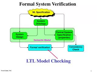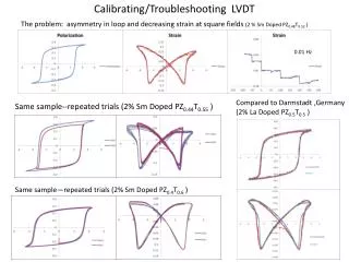
Mechanical System Verification LVDT Calibration
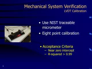
Mechanical System Verification LVDT Calibration. Use NIST traceable micrometer Eight point calibration. Acceptance Criteria Near zero intercept R-squared > 0.99. Mechanical System Verification Load Cell Zero. Use strain indicator Measure load cell zero reading

Mechanical System Verification LVDT Calibration
E N D
Presentation Transcript
Mechanical System VerificationLVDT Calibration • Use NIST traceable micrometer • Eight point calibration • Acceptance Criteria • Near zero intercept • R-squared > 0.99
Mechanical System VerificationLoad Cell Zero • Use strain indicator • Measure load cell zero reading • Used to determine if load cell has been fatigued or overstrained • Acceptance Criteria • Zero reading < 1.5 % of full-scale sensitivity
Mechanical System VerificationLoad Cell Calibration Certificates • Check laboratory documentation to determine last NIST traceable calibration • Acceptance Criteria • NIST traceable calibration within one year
Mechanical System VerificationLoad Cell Calibration Verification • Requires NIST traceable proving rings • Utilizes static loading • Verifies load cell calibration • Measures unwanted friction • Measures unwanted bending and deflections
Mechanical System VerificationLoad Cell Calibration Verification • Procedure • Apply static (ramp) load from 10 - 90% of proving ring capacity @ 10% intervals • Register load cell/LVDT readings with data acquisition system • Read dial gauge on proving ring
Mechanical System VerificationLoad Cell Calibration Verification • Acceptance Criteria • Proving ring versus load cell value within ± 5% of each other • Proving ring dial gauge versus LVDT reading within ± 5% of each other
Mechanical System VerificationDynamic Response • Verify overall equipment ability to conduct Resilient Modulus testing • Verify data acquisition process • Verify data format
Mechanical System VerificationDynamic Response • Procedure • Remove dial gauge from proving ring • Use external LVDTs or internally mounted LVDT for displacement measurements • Apply haversine shaped load pulse (.1 seconds on, .9 seconds off)
Mechanical System VerificationDynamic Response • Procedure (continued) • Apply dynamic load from 10 - 90% of proving ring capacity @ 10% intervals • Read deformation using data acquisition system
Mechanical System VerificationDynamic Response • Acceptance Criteria • Generated haversine close to ideal • Deformation response close to haversine • Deformation within 5% of standard • R-square > 0.99 • .002 second or less phase shift between load and deformation • Ymax/Ymin < 1.10 (10%)
Mechanical System VerificationPhase Angles • Dynamic sinusoidal tests • Verify overall system electronics (phase angle measurements) • Detect misalignment problems through the use of phase angle measurements • Acceptance Criteria • Phase angle < 2.8 degrees
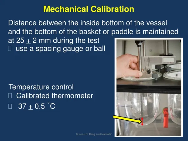
Mechanical System VerificationTriaxial Pressure Chamber • Procedure • Use autonomous pressure reading device to verify pressure • Acceptance Criteria • Gauge readings ± 2.5 % of target values • Hold for 10 minutes
The 3-Phase Startup Process • Verification of Electronic System • Verification of Mechanical System • Verification of Laboratory Ability to Conduct P46 Resilient Modulus Test
Laboratory Proficiency Testing • Focuses on laboratory ability (personnel/equipment) • Sample preparation • Operator’s ability to conduct a test • Proper sequence and magnitude of loading • Proper data format • Analysis of raw data to detect any discrepancies • Investigation of within and between laboratory variability
Laboratory Proficiency Testing • Acceptance Criteria • Vertical deformations within 30% • Approval by Representative based on visual observations • Conformance to all aspects of the protocol • Haversine wave form close to ideal • Deformation response reasonable • Resilient Modulus relationship reasonable
PRESENTATION OBJECTIVES • What is the Resilient Modulus (Mr) Startup Procedure Product Line • Why Mr Testing and the Startup Procedure is Important • Development of the Mr Startup Procedure • How to Conduct the Mr Startup Procedure • How to Get Information on the Mr Testing and Startup Product Line Who Should Use the Mr Testing and Startup Product Line and Why
Who Should Use the Product? • Any organization performing resilient modulus testing • State DOT’s • Universities • Consultant laboratories • Can be used for other tests as well • Complex modulus • Creep compliance • Indirect tensile testing, etc.
When Should Product Be Used? • General • Prior to starting a testing program • Every year during production testing • After a period of system inactivity • Other recommendations • Verify the operation of older machines for new applications • When equipment is replaced • When equipment is moved • Whenever a suspected overload or malfunction occurs
Uncover and Avoid Problems Electronics • Over-ranged load cell • Inadequate filters • Amplitude roll off: 2 Hz - 50 Hz • Unmatched filters • Excessive time delay (phase angle) between channels • Filters on and off
Uncover And Avoid Problems Software • Software not controlling the load adequately • Inadequate sampling rate • Raw data with no units • Automatic gain control, error range too big • Lack of gain control adjustment during testing • Improper raw data format - command values were saved rather than the feedback values
Uncover And Avoid Problems Mechanical • System not fast enough to apply proper haversine loads - complete upgrade of signal conditioning and control • Oversize servo-value • Friction in servo-value piston • Friction in triaxial cell seals • Misalignment caused by improperly designed triaxial cell fixture • Excessive deformation, up to 76% of total deformation due to bending of triaxial cell base plate
Uncover And Avoid Problems Mechanical (continued) • Excessive deformation due to unrestrained triaxial cell • Slippage of LVDT holders • Lack of control of pressure transducer • Malfunction of air pressure regulator
Benefits of Use • Provides guidelines for standardization of test process • Provides a benchmark performance standard for equipment • Minimizes equipment and operator variability • Promotes greater confidence in resilient modulus testing and resulting pavement design
Current Status of Product • P46 test procedure established • Videos produced and distributed • Startup procedure published • Startup procedures completed • FHWA • Kansas • North Carolina • Minnesota • University of Rhode Island • Consultant laboratories
PRESENTATION OBJECTIVES • What is the Resilient Modulus (Mr) Startup Procedure Product Line • Why Mr Testing and the Startup Procedure is Important • Development of the Mr Startup Procedure • How to Conduct the Mr Startup Procedure • Who Should Use the Mr Startup Procedure and Why How to Get Information on the Mr Startup Procedure?
Get and Use Mr Testing and Startup Procedure Product Line • Download procedure manuals from • LTPP homepage at www.tfhrc.gov • Order procedure manuals/videos: • Through LTPP homepage • Through LTPP customer service • (Tel Number: 865-481-2967)