Download
1 / 41
410 likes | 565 Vues
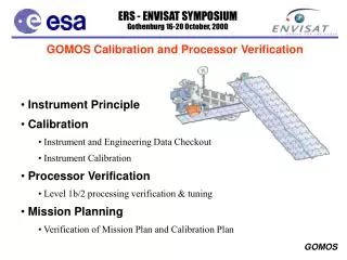
SCIAMACHY calibration verification at KNMI. Topics: Geolocation Polarisation correction Reflectance Limb radiance Effect on total ozone (DOAS) Ronald van der A, Juan Acarreta, Henk Eskes, Jeroen van Gent, Martin de Graaf, Piet Stammes, Gijs Tilstra. Geolocation.

E N D
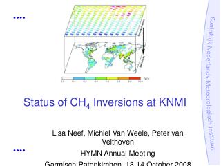
SCIAMACHY calibration verificationat KNMI Topics: • Geolocation • Polarisation correction • Reflectance • Limb radiance • Effect on total ozone (DOAS) Ronald van der A, Juan Acarreta, Henk Eskes, Jeroen van Gent, Martin de Graaf, Piet Stammes, Gijs Tilstra
Geolocation • Corner coordinates of the normal pixels and the PMD pixels (in nadir) have changed in the new dataset of orbits 2509/2510, as compared to the 2002 dataset. - Max. change: 0.0031 degree in latitude / 0.0460 degree in longitude - Mean change: -0.0010 degree in latitude /-0.0016 degree in longitude • There is a small difference in pixel time (of order 0.05 sec) between the old (2002) and the new dataset. • Centre longitudes on the date line (180 deg longitude): There is an error in the calculation of the centre-of-pixel longitude in the current operational NRT level1 data files (jumps of 90, 180, 270 degree). Probably the corner averaging is wrong. Has this been fixed in version 4.02?
Viewing angle, Solar Zenith angle Note: TOA height = 100 km ?! (gives non-negligible VZA angle errors of ~ 0.2 degree)
Conclusions on geolocation • Change in time and coordinates. Reason ? • Coordinates were checked with islands; accurate < < PMD pixel size • SZA and VZA are now both given at 100 km
Polarisation correction in nadir • Polarisation correction step in 1b > 1c uses the measured Q and U values determined by 0-1b processor. • If there is an error in Q and U, it will affect the polarisation correction, and thus the reflectance. • Q and U are largest for east pixels, and if SZA is large. • Q and U are smallest for west pixels, and for small SZA. • Easy discrimator: the polarisation bump around 350 nm should not be seen in the polarisation corrected spectra !
Selection of states:state 3=Bjelorus (SZA=44 deg) state 6=Sahara (SZA=30 deg)
State 6 (Sahara): Effect of UV polarisation correctionblue=polarisation correction off; green=on old New, 2.2 east west New, 2.4 New, 3.0
State 3 (Bjelorus.): Effect of UV polarisation correctionblue=polarisation correction off; green=on old New, 2.2 New, 2.4 New, 3.0
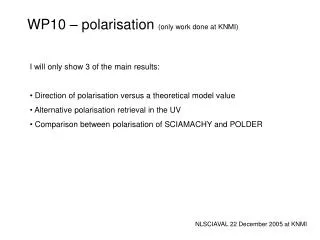
Direction of polarisation (U/Q) POLDER measurements vs single Rayleigh scattering theory: Conclusion: use ratio U/Q from theory and not from PMD msms. ! (in the data processor, shift 550 nm > 2500 nm)
Conclusions on polarisation correction • The polarisation correction in nadir has become worse in the new processing. See the 350 nm bump. • Version 3.0 is the worst. The old 2002 polarisation correction is the better of the 4 types; version 2.4 seems comparable in quality. • The ratio U/Q mustbe taken from single scattering theory for all wavelengths, because the 45o PMD measurement is not accurate. This requires a simple input parameter change in the 0-1b processing.
In-flight reflectance verification Reflectance = Earth radiance / 0 solar irradiance Previous approaches used: • comparison with DAK radiative transfer model: SCIA is about 20 % too low from 300-400 nm (published by Tilstra et al. in Dec. 2002) • comparison with GOME colocated data: SCIA is about 10-20 % too low from 400-800 nm(RAL; published by Tilstra et al. in Oct. 2003) New approach: Comparison with colocated reflectances from MERIS (work by Juan Acarreta).
MERIS-SCIAMACHY comparison Used MERIS channels: 442, 510, 665, 708, and 885 nm. Each of these channels falls within one spectral cluster of SCIAMACHY with 30x60 km2 resolution. Steps: 1. Spatial integration of MERIS: Integrate reflectance of MERIS pixels (about 0.5x0.5 km2) over SCIAMACHY pixel area (30x60 km2). 2. Spectral integration of SCIA: Integrate SCIAMACHY reflectance over MERIS slit function (about 10 nm wide). 3. Compare the resulting MERIS and SCIAMACHY reflectances.
SCIAMACHY and MERIS observations "mixed" sahara clouds
Example of three MERIS images S-Atlantic Ocean cloudy Spain - mixed Sahara - clear
SAHARA 442 Viewing Angle Viewing angle variation: Blue=300 …….. Red=00
MIXED 442 Viewing Angle
SAHARA 885 Viewing Angle
CLOUDS 885 Viewing Angle
MIXED 885 Viewing Angle
Conclusions on reflectance 1. The new processor + key data did not change the radiometric calibration (without polarisation correction), as expected. 2. SCIAMACHY reflectance improvement could come from in-flight comparison with other satellites and radiation models. 3. Do not change the solar spectrum to correct the reflectance, because this causes confusion! The SCIAMACHY radiance and irradiance have their own calibrations, which have their own errors. Instead, change the reflectance itself. 4. By comparing SCIAMACHY with MERIS at 442, 510, 665, 708, and 885 nm, the SCIA reflectance appears to be about 20 % lower than that of MERIS, in agreement with comparisons with GOME and DAK. 5. For low reflectances, the ratio MERIS/SCIA is different; this could be due to different gain for dark scenes in MERIS (ocean colour mode). 6. No scan angle dependence of MERIS/SCIA slope! This means that an angle-independent correction of reflectance suffices. et of -0.01 reflectance units
7. We propose to apply anin-flight reflectance correction factorto SCIAMACHY from MERIS, GOME, DAK. This factor is different from the “compensation factor” of J. Frerick (email of 8 Dec. 2003). To correct SCIAMACHY calibration requires: corrected RSCIA = intercept+ slopeRSCIA • Intercept = 0.01 (about 0) • Slope = 1.14 – 1.25 (depends on wavelength) • For 400-800 nm use MERIS calibration. • For 300-400 nm use GOME/DAK comparisons.
SCIAMACHY reflectance corrrection - comparison of different aproaches Correction factor for SCIAMACHY reflectance
Error in units • There is still an error in the units of the error on the calibrated Earth radiance: the error is in BU. This error has a very smooth behaviour. It is probably not the real error.
Effect of new calibration on ozone DOAS retrievals (work by Henk Eskes and Ronald v.d. A) Approach: Total ozone retrieval using TOSOMI algorithm including cloud detection using FRESCO. Viewing angle is always checked and corrected.
Bias: -0.01 DU Std: 1.3 DU Total ozone ratio vs. latitude
Total ozone ratio vs. latitude Bias: 0.05 DU Std: 0.18 DU
Total ozone ratio vs. latitude Bias: 0.04 DU Std: 0.58 DU
Total ozone ratio vs. viewing angle East West
Total ozone ratio - influence of polarisation in east pixels? East West
Conclusions on ozone DOAS fitting • • Ozone differences versions 2.2 vs 2.4 vs 3.0: • rms ~ 0.5 DU, bias negligible • • Ozone differences versions 2002 vs 2.2/3.0: • rms ~ 1.3 DU, bias negligible • • Cloud fraction / top pressure: very little change • Remaining viewing angle dependence due to TOA angle • difference and polarisation correction ? • The new data processor (like the old version) gives • sufficient quality in level 1 for ozone DOAS retrieval.
Limb radiance verification (work by J. van Gent) Old (2002) Profile of mean radiances of cluster 10 New, 2.2 Sun normalized limb radiances for processor versions 2002 and new (2.2). Wavelength average over 309-320 nm.
Rel. difference new 2.2 - old Comparison of limb radiances for processor 2002 and new (2.2). Cluster 10 (channel 2a, 309-320 nm) Differences in % w.r.t. processor version 2002
Rel. difference new 2.2 - old Comparison of limb radiances for processors 2002 and new (2.2). Cluster 30 (channel 6, 1000-1750 nm) Differences in % w.r.t. processor version 1.0
New 2.2 New, 3.0 Sun normalized limb radiances for processor versions 2.2 and 3.0. Wavelength average over 309-320 nm.
Rel. difference 3.0 – 2.2 Comparison of limb radiances for new processor with keydata 2.2 and 3.0. Cluster 10 (channel 2a) Differences in % w.r.t. processor version 2.2
Rel. difference 3.0 – 2.2 Comparison of limb radiances for new processor with keydata 2.2 and 3.0. Cluster 30 (channel 6) Differences in % w.r.t. processor version 2.2
Conclusions on limb radiances • The difference between the 2002 processor and the new processor with keydata v.2.2 is larger than between the different key data versions of the new processor.