Understanding RS-232 Communication: Voltage Levels and UART Transmitter Design
This document covers the fundamentals of RS-232 communication, outlining the voltage levels used, where +5.5V represents logic 0 and -5.5V represents logic 1. It details the loop feedback between a PC (DTE) with a female connector and a Spartan-3 board (DCE) with a male connector, using a straight-through cable. The UART transmitter design is explained, including the transmit state diagram in VHDL and the process of transmitting 8-bit parallel data to serial format through a TxD line. Additionally, it includes standard ASCII codes for reference.

Understanding RS-232 Communication: Voltage Levels and UART Transmitter Design
E N D
Presentation Transcript
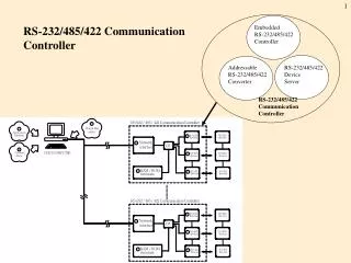
RS-232 Port Discussion D12.1
RS-232 voltage levels: +5.5 V (logic 0) -5.5 V (logic 1) Loop feedback
PC: DTE female connector Spartan-3 board: DCE male connector Straight-through cable
Note: TxD (pin 2) on Spartan-3 DCE connector is connected to RD (pin 2) on the PC DTE connector
Table 9.2 Standard ASCII codes Dec 0 16 32 48 64 80 96 112 Hex 0 1 2 3 4 5 6 7 0 0 NUL DLE blank 0 @ P p 1 1 SOH DC1 ! 1 A Q a q 2 2 STX DC2 " 2 B R b r 3 3 ETX DC3 # 3 C S c s 4 4 EOT DC4 $ 4 D T d t 5 5 ENQ NAK % 5 E U e u 6 6 ACK SYN & 6 F V f v 7 7 BEL ETB ' 7 G W g w 8 8 BS CAN ( 8 H X h x 9 9 HT EM ) 9 I Y i y 10 A LF SUB * : J Z j z 11 B VT ESC + ; K [ k { 12 C FF FS , < L \ l | 13 D CR GS - = M ] m } 14 E SO RS . > N ^ n ~ 15 F SI US / ? O _ o DEL Standard ASCII Codes
How would you make the following hardware Tx UART? 8-bit parallel data comes in tx_data(7:0) and is loaded into a transmit buffer txbuff when tdre is high. When ready goes high the contents of txbuff is sent out TxD as asynchronous serial data. When txbuff is empty, tdre is set to 1.
VHDLCanonical Sequential Network init Combinational Network s(t+1) s(t) State Register next state present state x(t) present input process(clk, init) present output clk z(t) process(present_state, x)
VHDLMealy Machine process(present_state, x) init C1 C2 s(t+1) State Register next state s(t) z(t) present state x(t) present input process(present_state, x) clk process(clk, init)
VHDLMoore Machine init C2 C1 z(t) s(t+1) State Register next state s(t) present state x(t) present input process(present_state, x) process(present_state) clk process(clk, init)
VHDLCanonical Sequential Network init Combinational Network s(t+1) s(t) State Register next state present state x(t) Combine into a single process present input process(clk, init) present output clk z(t) process(present_state, x)
entity uart_tx is port( clk : in STD_LOGIC; clr : in STD_LOGIC; tx_data : in STD_LOGIC_VECTOR(7 downto 0); ready : in STD_LOGIC; tdre : out STD_LOGIC; TxD : out STD_LOGIC ); end uart_tx;
architecture uart_tx of uart_tx is type state_type is (mark, start, delay, shift, stop); signal state: state_type; signal txbuff: STD_LOGIC_VECTOR (7 downto 0); signal baud_count: STD_LOGIC_VECTOR (11 downto 0); signal bit_count: STD_LOGIC_VECTOR (3 downto 0); constant bit_time: STD_LOGIC_VECTOR (11 downto 0) := X"A28"; begin 9600 baud
uart2: process(clk, clr, ready) begin if clr = '1' then state <= mark; txbuff <= "00000000"; baud_count <= X"000"; bit_count <= "0000"; TxD <= '1'; elsif (clk'event and clk = '1') then case state is when mark => -- wait for ready bit_count <= "0000"; tdre <= '1'; if ready = '0' then state <= mark; txbuff <= tx_data; else baud_count <= X"000"; state <= start; -- go to start end if;
when start => -- output start bit baud_count <= X"000"; TxD <= '0'; tdre <= '0'; state <= delay; -- go to delay when delay => -- wait bit time tdre <= '0'; if baud_count >= bit_time then baud_count <= X"000"; if bit_count < 8 then -- if not done state <= shift; -- go to shift else -- else state <= stop; -- go to stop end if; else baud_count <= baud_count + 1; state <= delay; -- stay in delay end if;
when shift => -- get next bit tdre <= '0'; TxD <= txbuff(0); txbuff(6 downto 0) <= txbuff(7 downto 1); bit_count <= bit_count + 1; state <= delay; when stop => -- stop bit tdre <='0'; TxD <= '1'; if baud_count >= bit_time then baud_count <= X"000"; state <= mark; else baud_count <= baud_count + 1; state <= stop; end if; end case; end if; end process uart2; end uart_tx;
Test Transmit UART Set slide switches to some ASCII code and then press button 0 to send ASCII code out serial port. SW BTN(0)
entity tx_tst_ctrl is port( clk : in STD_LOGIC; clr : in STD_LOGIC; btn : in STD_LOGIC; tdre : in STD_LOGIC; ready : out STD_LOGIC ); end tx_tst_ctrl;
architecture tx_tst_ctrl of tx_tst_ctrl is type state_type is (wtbtndn, wttdre, load, wtbtnup); signal state: state_type; begin ctrl: process(clk, clr, btn, tdre) begin if clr = '1' then state <= wtbtndn; ready <= '0'; elsif (clk'event and clk = '1') then case state is when wtbtndn => -- wait for btn if btn = '0' then -- if bnt up state <= wtbtndn; -- stay in wtbtndo ready <= '0'; else ready <= '0'; state <= wttdre; -- else go to wttdre end if;
when wttdre => -- wait for tdre = 1 if tdre = '0' then -- if tdre = 0 state <= wttdre; -- stay in wtdone ready <= '0'; else state <= load; -- else go to load ready <= '0'; end if; when load => -- output ready ready <= '1'; state <= wtbtnup; -- go to wtbtnup
when wtbtnup => -- wait for btn up if btn = '1' then -- if btn down state <= wtbtnup; -- stay in wtbtnup ready <= '0'; else ready <= '0'; state <= wtbtndn; -- else go to wtbtndn end if; end case; end if; end process ctrl; end tx_tst_ctrl;
Test Transmit UART Top-level design entity uart_tx_test is port ( mclk : in STD_LOGIC; sw : in STD_LOGIC_VECTOR(7 downto 0); btn : in STD_LOGIC_VECTOR(3 downto 0); ld : out STD_LOGIC_VECTOR(7 downto 0); TxD : out STD_LOGIC ); end uart_tx_test; Pin "R13"
architecture uart_tx_test_arch of uart_tx_test is component uart_tx port( clk : in STD_LOGIC; clr : in STD_LOGIC; tx_data : in STD_LOGIC_VECTOR(7 downto 0); ready : in STD_LOGIC; tdre : out STD_LOGIC; TxD : out STD_LOGIC ); end component; component tx_tst_ctrl port( clk : in STD_LOGIC; clr : in STD_LOGIC; btn : in STD_LOGIC; tdre : in STD_LOGIC; ready : out STD_LOGIC ); end component;
component debounce4 port( clk : in std_logic; clr : in std_logic; inp : in std_logic_vector(3 downto 0); outp : out std_logic_vector(3 downto 0)); end component; signal clr, clk, cclk: std_logic; signal tdre, ready: std_logic; signal clkdiv : std_logic_vector(23 downto 0); signal btnd : std_logic_vector(3 downto 0); begin
-- Divide the master clock (50Mhz) down to a lower frequency. process (mclk) begin if clr = '1' then clkdiv <= "000000000000000000000000"; elsif mclk = '1' and mclk'Event then clkdiv <= clkdiv + 1; end if; end process; clk <= clkdiv(0); -- 25 MHz cclk <= clkdiv(17); -- 190 Hz ld(7) <= btnd(1); ld(6) <= btnd(2); ld(5) <= btnd(1); ld(4) <= btnd(2); ld(3) <= btnd(1); ld(2) <= btnd(2); ld(1) <= btnd(1); ld(0) <= tdre; clr <= btnd(3);
U1: uart_tx port map (TxD => TxD, clk => clk, clr => clr, ready => ready, tx_data => sw, tdre => tdre); U2: tx_tst_ctrl port map (clk => clk, clr => clr, btn => btnd(0), tdre => tdre, ready => ready); U3 : debounce4 port map( clk => cclk, clr => clr, inp => btn, outp => btnd ); end uart_tx_test_arch; btn(0) sw
How would you make the following hardware Rx UART? 8-bit asynchronous serial data comes in RxD and fills up the shift register data_rx. When data_rx is full, rdrf is set to 1. rdrf is cleared to zero by bringing clrflg high. The framing error flag FE is set to 1 if the stop bit is not 1.
entity uart_rx is port( RxD : in STD_LOGIC; clk : in STD_LOGIC; clr : in STD_LOGIC; rdrf_clr : in STD_LOGIC; rdrf : out STD_LOGIC; FE : out STD_LOGIC; rx_data : out STD_LOGIC_VECTOR(7 downto 0) ); end uart_rx;
architecture uart_rx of uart_rx is type state_type is (mark, start, delay, shift, stop); signal state: state_type; signal rxbuff: STD_LOGIC_VECTOR (7 downto 0); signal baud_count: STD_LOGIC_VECTOR (11 downto 0); signal bit_count: STD_LOGIC_VECTOR (3 downto 0); signal rdrf_set, fe_set, cclr, cclr8, rxload: STD_LOGIC; constant bit_time: STD_LOGIC_VECTOR (11 downto 0) := X"A28"; constant half_bit_time: STD_LOGIC_VECTOR (11 downto 0) := X"514"; begin 9600 baud
uart2: process(clk, clr, rdrf_clr) begin if clr = '1' then state <= mark; rxbuff <= "00000000"; baud_count <= X"000"; bit_count <= "0000"; FE <= '0'; elsif rdrf_clr = '1' then rdrf <= '0'; elsif (clk'event and clk = '1') then case state is when mark => -- wait for start bit baud_count <= X"000"; bit_count <= "0000"; if RxD = '1' then state <= mark; else FE <= '0'; state <= start; -- go to start end if;
when start => -- check for start bit if baud_count >= half_bit_time then baud_count <= X"000"; state <= delay; else baud_count <= baud_count + 1; state <= start; end if; when delay => if baud_count >= bit_time then baud_count <= X"000"; if bit_count < 8 then state <= shift; else state <= stop; end if; else baud_count <= baud_count + 1; state <= delay; end if;
when shift => -- get next bit rxbuff(7) <= RxD; rxbuff(6 downto 0) <= rxbuff(7 downto 1); bit_count <= bit_count + 1; state <= delay; when stop => rdrf <= '1'; if RxD = '0' then FE <= '1'; else FE <= '0'; end if; state <= mark; end case; end if; end process uart2; rx_data <= rxbuff; end uart_rx;
Test Receive UART Receive ASCII code sent from terminal program on PC when key is pressed and display on LEDs.
Test Transmit UART Echo back ASCII code sent from PC. rdrf_clr
entity test2_rx_ctrl is port( clk : in STD_LOGIC; clr : in STD_LOGIC; rdrf : in STD_LOGIC; rdrf_clr : out STD_LOGIC ); end test2_rx_ctrl; architecture test2_rx_ctrl of test2_rx_ctrl is type state_type is (wtrdrf, load); signal state: state_type;
begin ctrl: process(clk, clr, rdrf) begin if clr = '1' then state <= wtrdrf; rdrf_clr <= '0'; elsif (clk'event and clk = '1') then case state is when wtrdrf => rdrf_clr <= '0'; if rdrf = '0' then state <= wtrdrf; else state <= load; end if; when load => rdrf_clr <= '1'; state <= wtrdrf; end case; end if; end process ctrl; end test2_rx_ctrl;
Top-level test of UART entity uart_test2 is port ( mclk : in STD_LOGIC; BTN3 : in STD_LOGIC; RxD : in STD_LOGIC; LD : out STD_LOGIC_VECTOR(7 downto 0); TxD : out STD_LOGIC ); end uart_test2; architecture uart_test2_arch of uart_test2 is component uart_tx port( clk : in STD_LOGIC; clr : in STD_LOGIC; tx_data : in STD_LOGIC_VECTOR(7 downto 0); ready : in STD_LOGIC; tdre : out STD_LOGIC; TxD : out STD_LOGIC ); end component;
component tx_tst_ctrl port( clk : in STD_LOGIC; clr : in STD_LOGIC; btn : in STD_LOGIC; tdre : in STD_LOGIC; ready : out STD_LOGIC ); end component; component uart_rx port( RxD : in STD_LOGIC; clk : in STD_LOGIC; clr : in STD_LOGIC; rdrf_clr : in STD_LOGIC; rdrf : out STD_LOGIC; FE : out STD_LOGIC; rx_data : out STD_LOGIC_VECTOR(7 downto 0) ); end component;
component test2_rx_ctrl port( clk : in STD_LOGIC; clr : in STD_LOGIC; rdrf : in STD_LOGIC; rdrf_clr : out STD_LOGIC ); end component; signal clr, clk, cclk: std_logic; signal tdre, rdrf, rdrf_clr, FE, ready, btn: std_logic; signal clkdiv : std_logic_vector(23 downto 0); signal data : std_logic_vector(7 downto 0);
begin -- Divide the master clock (50Mhz) down to a lower frequency. process (mclk) begin if clr = '1' then clkdiv <= "000000000000000000000000"; elsif mclk = '1' and mclk'Event then clkdiv <= clkdiv + 1; end if; end process; clk <= clkdiv(0); -- 25 MHz cclk <= clkdiv(17); -- 190 Hz LD <= data; clr <= BTN3; btn <= rdrf_clr;
U1: uart_tx port map (TxD => TxD, clk => clk, clr => clr, ready => ready, tx_data => data,tdre => tdre); U2: uart_rx port map (RxD => RxD, clk => clk, clr => clr, rdrf_clr => rdrf_clr, rx_data => data,rdrf => rdrf, FE => FE); U3: tx_tst_ctrl port map (clk => clk, clr => clr, tdre => tdre, btn => btn, ready => ready); U4: test2_rx_ctrl port map (clk => clk, clr => clr, rdrf => rdrf, rdrf_clr => rdrf_clr); end uart_test2_arch;