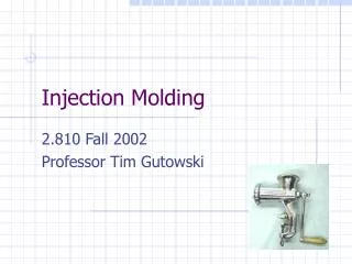
Injection Molding
Injection Molding. 2.810 Fall 2002 Professor Tim Gutowski. 1862 first synthetic plastic 1866 Celluloid 1891 Rayon 1907 Bakelite 1913 Cellophane 1926 PVC 1933 Polyethylene 1938 Teflon 1939 Nylon stockings 1957 velcro 1967 “The Graduate”. Short history of plastics. Outline.

Injection Molding
E N D
Presentation Transcript
Injection Molding 2.810 Fall 2002 Professor Tim Gutowski
1862 first synthetic plastic 1866 Celluloid 1891 Rayon 1907 Bakelite 1913 Cellophane 1926 PVC 1933 Polyethylene 1938 Teflon 1939 Nylon stockings 1957 velcro 1967 “The Graduate” Short history of plastics
Outline • Basic operation • Cycle time and heat transfer • Flow and solidification • Part design • Tooling • New developments • Environment
Readings • Tadmore and Gogos • Molding and Casting pp584 -610 • Boothroyd Dewhurst • Design for Injection Molding pp 319 - 359 • Kalpakjian see Ch 18 • Injection molding case study;Washing machine augers; see on web page
30 ton, 1.5 oz (45 cm3) Engel Injection Molding Machine for wheel fabrication
* Schematic of thermoplastic Injection molding machine Process & machine schematics * * Source: http://www.idsa-mp.org/proc/plastic/injection/injection_process.htm
Process Operation • Temperature: barrel zones, tool, die zone • Pressures: injection max, hold • Times: injection, hold, tool opening • Shot size: screw travel Processing window Temp. Thermal degradation Flash Short-shot Melt Pressure
Time(sec) Time(sec) Typical pressure/temperature cycle * * Cooling time generally dominates cycle time * Source: http://islnotes.cps.msu.edu/trp/inj/inj_time.html
Calculate clamp force, & shot size F=P X A = 420 tons 3.8 lbs = 2245 cm3 =75 oz Actual ; 2 cavity 800 ton
Heat transfer Note; aTool>apolymer 1-dimensional heat conduction equation : qx qx + Dqx Fourier’s law Boundary Conditions: The boundary condition of 1st kind applies to injection molding since the tool is often maintained at a constant temperature
Tii t TW x -L +L Heat transfer Let Lch = H/2 (half thickness) = L ; tch = L2/a ; DTch = Ti – TW (initial temp. – wall temp.) Non-dimensionalize: Dimensionless equation: Initial condition Boundary condition Separation of variables ; matching B.C.; matching I.C.
Temperature in a slab Centerline, q = 0.1, Fo = at/L2 = 1 Bi-1 =k/hL
Reynolds Number Reynolds Number: For typical injection molding For Die casting * Source: http://www.idsa-mp.org/proc/plastic/injection/injection_process.htm
F v F/A h m 1 v/h Viscous Shearing of Fluids Newtonian Viscosity Generalization: Typical shear rate for Polymer processes (sec)-1 Extrusion 102~103 Calendering 10~102 Injection molding 103~104 Comp. Molding 1~10 Injection molding “Shear Thinning” ~ 1 sec-1 for PE
Viscous Heating Rate of Heating = Rate of Viscous Work Rate of Temperature rise Rate of Conduction out Brinkman number For injection molding, order of magnitude ~ 0.1 to 10
Non-Isothermal Flow Flow rate: 1/t ~V/Lx v Heat transfer rate: 1/t ~a/(Lz/2)2 Small value => Short shot For injection molding For Die casting of aluminum * Very small, therefore it requires thick runners
Fountain Flow * ** * Source: http://islnotes.cps.msu.edu/trp/inj/flw_froz.html ; ** Z. Tadmore and C. Gogos, “Principles of Polymer Processing”
Shrinkage distributions Transverse direction sample V=3.5cm/s V=8cm/s * Source: G. Menges and W. Wubken, “Influence of processing conditions on Molecular Orientation in Injection Molds”
Gate Location and Warping Shrinkage Direction of flow – 0.020 in/in Perpendicular to flow – 0.012 2.0 60 1.96 Sprue 60.32 1.976 2.0 Before shrinkage After shrinkage Air entrapment Gate Center gate: radial flow – severe distortion Edge gate: warp free, air entrapment Diagonal gate: radial flow – twisting End gates: linear flow – minimum warping
LDPE 0.030 Acetal 0.030 LDPE PP PP with flow 0.025 0.025 Acetal 0.020 PP across flow 0.020 Nylon 6/6 0.015 Nylon 6/6 Shrinkage Shrinkage 0.015 0.010 0.005 PMMA 0.010 0.000 6000 10000 14000 18000 0.005 8000 12000 16000 PMMA Pressure on injection plunger (psi) 0.000 100 120 140 160 180 200 220 240 Mold Temperature (F) Effects of mold temperature and pressure on shrinkage
Sink mark Weld line, Sink mark Gate Weld line Mold Filling Solidified part Basic rules in designing ribs to minimize sink marks * Source: http://www.idsa-mp.org/proc/plastic/injection/injection_design_7.htm
* * Injection Molding * Source: http://www.idsa-mp.org/proc/plastic/injection/injection_design_2.htm
Where is injection molding? DLtotal = DLmold + DLshrinkage
LDPE 0.030 Acetal PP with flow 0.025 0.020 PP across flow 0.015 Nylon 6/6 Shrinkage 0.010 0.005 PMMA 0.000 6000 10000 14000 18000 8000 12000 16000 Pressure on injection plunger (psi) Effects of mold temperature and pressure on shrinkage
Nozzle Sprue Tooling Basics Core Plate Cavity Plate Moulding Core Cavity Basic mould consisting of cavity and core plate Cavity Runner Gate Melt Delivery
Nozzle Knob Runner Cavity Part Stripper plate Core Tooling for a plastic cup
Knob Nozzle Nozzle Runner Cavity Runner Cavity Cavity Part Part Part Stripper plate Tooling for a plastic cup
Tooling * * * * * ** * * Source: http://www.idsa-mp.org/proc/plastic/injection/; ** http://www.hzs.co.jp/english/products/e_trainer/mold/basic/basic.htm (E-trainer by HZS Co.,Ltd.)
Part design rules • Simple shapes to reduce tooling cost • No undercuts, etc. • Draft angle to remove part • In some cases, small angles (1/4) will do • Problem for gears • Even wall thickness • Minimum wall thickness ~ 0.025 in • Avoid sharp corners • Hide weld lines • Holes may be molded 2/3 of the way through the wall only, with final drilling to eliminate weld lines
New developments ; injection molding with cores Injection Molded Housing shown in class Cores used in Injection Molding Cores and Part Molded in Clear Plastic
Environmental issues • Petroleum and refining • Primary processing • Out gassing & energy during processing • End of life
Environmental loads by manufacturing sector EPA 2001, DOE 2001
The estimated environmental performance of various mfg processes (not including auxiliary requirements) *Energy per wt. normalized by the melt energy ** total raw mat’l normalized by the part wt.
Summary • Basic operation • Cycle time and heat transfer • Flow and solidification • Part design • Tooling • New developments • Environment