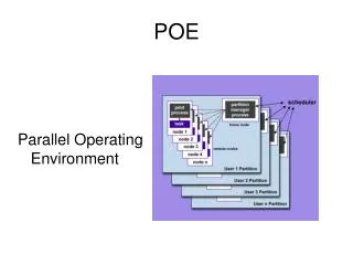
Truss Problem and Trajectory Motion: Study, Analysis and Calculations
270 likes | 302 Vues
This problem involves the study and analysis of a truss system, including calculating the length of a truss member and determining the magnitude and type of force being carried by another member. It also includes solving a trajectory motion problem involving a motorcyclist's take-off angle and horizontal distance traveled. Additionally, it covers the basic concepts of materials testing and the stress-strain curve. The problem provides step-by-step calculations and explanations.

Truss Problem and Trajectory Motion: Study, Analysis and Calculations
E N D
Presentation Transcript
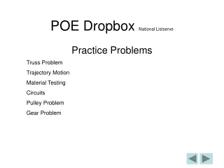
POE Dropbox National Listserve Truss Problem Trajectory Motion Material Testing Circuits Pulley Problem Gear Problem Practice Problems
Figure 1 Figure 2 Truss Problem Study the truss in Figure 1 and its free body diagram in Figure 2, and answer the following questions. How many reaction forces are present in this truss system? 3; FAX, FAY, FBY
Figure 1 Figure 2 Truss Problem • Calculate the length of truss member BC. • What do we know from looking at Figure 1 & 2? • Length of AC = 4 feet • Angle between AC and BC is 30° • What can you use to solve for the length of BC? (SOHCAHTOA) • Use Cosine θ!
Figure 1 Figure 2 A 4 ft C 30° B Truss Problem AC = 4 ft, θ= 30° Cos θ= adjacent/hypotenuse 0.866 = BC/4ft BC = 3.464 ft
3.464 ft. Figure 1 Figure 2 Truss Problem C. Using joint C, determine the magnitude and type of force (tension or compression) that is being carried by truss member BC.
C FAC 30° FBC F1 = 100 lbs. Truss Problem C. Using joint C, determine the magnitude and type of force (tension or compression) that is being carried by truss member BC. F1= 100 lbs. E: ∑FCY = 0 -Fcy + FBC = 0 -100 lbs. + FBC (sin 210°) = 0 FBC (sin 210°) = 100 lbs. FBC = - 200 lbs. FBC = 200 lbs. (compression)
Trajectory Motion There are few concepts that you need to understand to get through this problem. Let’s start by defining kinematics…… • Kinematics is the study of motion allowing us to predict the path of an object when traveling at some angle with respect to the Earth’s surface.
Take-off angle = 37° Take-off speed = 52 ft/sec 52 ft/sec 37° VIX Trajectory Motion What was the motorcyclist’s initial horizontal velocity? VIX (horizontal velocity) What equation is used to calculate horizontal velocity? VIX = VI cosine θ VIX = 52 ft/sec cos 37° VIX = 41.52 ft/sec
Take-off angle = 37° Take-off speed = 52 ft/sec 52 ft/sec 37° VIX = 41.52 ft/sec Trajectory Motion What was the horizontal distance between the take-off and landing points? Use -32.15 ft/sec2 for acceleration due to gravity. X = VI2sin(2*θ)/g X = (52 ft/sec)2 sin(2 * 37°) / 32.15 ft/sec2 X = 80.84 ft
Material Testing • Materials testing is basically divided into two major groups, destructive testing, and nondestructive testing. • Destructive testing is defined as a process where a material is subjected to a load in some manner which will cause that material to fail. • When non-destructive testing is performed on a material, the part is not permanently affected by the test, and the part is usually still serviceable. The purpose of that test is to determine if the material contains discontinuities (an interruption in the normal physical structure or configuration of a part) or defects (a discontinuity whose size, shape or location adversely affects the usefulness of a part). • During testing of a material sample, the stress–strain curve is created and shows a graphical representation of the relationship between stress, derived from measuring the load applied on the sample, and strain, derived from measuring the deformation of the sample
Stress-Strain Curve/ Diagram Stress at the proportional limit proportional limit Strain at the proportional limit • What is illustrated in a Stress-Strain Curve/ Diagram? • The proportional limit: The greatest stress at which a material is capable of sustaining the applied load without deviating from the proportionality of stress to strain • The stress at the proportional limit • The strain at the proportional limit
Properties of Materials Symbols • D – the change in • d – total deformation (length and diameter) • s – stress, force per unit area (psi) • e – strain (inches per inch) • E – modulus of elasticity, Young’s modulus (ratio of stress to strain for a given material or the measure of the stiffness of a material.) • P – axial forces (along the same line as an axis (coaxial) or centerline)
Properties of Materials Symbols • Formulas you might use: • σ = P/A (Stress) • = /L (Strain) • = PL/A (Total Deformation) • = σ/ (modulus of elasticity)
What are we solving for and what does our diagram provide us? We are solving for the force so use the equation F p. l. = A O x sp. l. What do we know from the diagram? sp. l. = 40,000 psi (Stress at proportional limit) Information from the problem statement? 0.2 in2 = cross sectional area (AO) 3. A test sample, having a cross-sectional area of 0.2 in2 and a 2 inch test length, was pulled apart in a tensile test machine. Figure 4 shows the resulting Stress-Strain diagram. Use the information in the diagram to answer the following questions. a. Calculate the force that the sample experienced at the proportional limit.
Now solve the problem: Calculate the force that the sample experienced at the proportional limit. AO = 0.2 in2, s=40,000 psi F p. l. = A O x sp. l. F p. l. =0.2 in2 x 40,000 psi F p. l. = 8,000 lbs.
3b. Starting at the origin and ending at the proportional limit, calculate the modulus of elasticity for this material. To solve this problem we are going to use the equation E = s/∈ ∈ = 0.005 in/in, s =40,000 psi E = s/∈ E = 40,000/ 0.005 E = 8,000,000 psi
A Basic Circuit Source = Battery Wire Load = Lamp Battery Lamp Conductor = Wire Control = Switch Switch There is only one path for the electrons to flow
A Series Circuit Wire Load = 2 Lamps Conductor = Wire 2 Lamps Source = Battery Battery Control = Switch Electrons can only flow along one path, and MUST go through each component before getting to the next one. Switch
A Parallel Circuit Source = Battery Load = 3 Lamps 3 Lamps Battery Conductor = Wire Control = Switch Switch Wire Two or more components are connected so that current can flow to one of them WITHOUT going through another
A Series-Parallel Circuit A combination of components both in Series and in Parallel
To measure current with a multimeter, the “leads” must be placed in series. To measure voltage with a multimeter, the “leads” must be placed in Parallel (across the load).
If the amount of current in the circuit is equal to 0.5A, what is the voltage value of the power supply? To solve the problem use the following equation: E = I * R ( Voltage = Current * Resistance) I = 0.5 A, R = 16.0 Ω E = 0.5 A * 16.0 Ω E = 8V
Heat Transfer Conduction: the flow of thermal energy through a substance from a higher- to a lower-temperature region. Convection: the transfer of heat by the circulation or movement of the heated parts of a liquid or gas. Radiation: the process in which energy is emitted as particles or waves. R-Value ability to resist the transfer of heat. The higher the R-Value, the more effective the insulation
Pulley Problem Figure 5 represents a belt driven system. Pulley B, which has a diameter of 16 inches, is being driven by Pulley A, which has a diameter of 4 inches. If Pulley A is spinning at 60 RPMs, then Pulley B is spinning at ______ RPMs. DIA of B= 16”, DIA of A=4, A RPM=60 DIA-B/DIA- A = RPM-B/RPM-A 16/4 = 60/B RPM 15 = B RPM
Gear Problem The gear train consists of a 40-tooth (input), 20-tooth, and 30-tooth (output) gear. If the input gear rotates 10 times, how many times will the output gear rotate? 40 g, 20 g, 30 g, Nin 10 Nin*R = Nout*R 40*10 = Nout*30 13.3 = Nout 40/20 = 2/1 *10 = 20 20/30 = 2/3 *5 = 20/3
Mechanisms The wheels on a bicycle have a 10” radius. If the bike must travel exactly 2000”, how many revolutions are required? Radius 10”, Dist.=2000” Distance/ Circumference = Revolutions (Circumference = π*Dia) 2000/ (3.14*20) = Rev. 31.8 Revolutions
Properties of Materials Figure 10 shows a 100 lb. normal force being applied to a 12” long x 10” diameter cylinder. What is the resulting compressive stress in the cylinder? F=100 lb., Dia.=10” 1) A = π * r2 2) S = F/A 1) A = 3.14 * 52 S = 100 lbs/78.5 in2 S = 1.27 psi