Download
1 / 30
300 likes | 321 Vues
Learn about VP switching where decisions are made based on VPI numbers, reducing admin workload and enabling faster switching of cells. VP tunnels aggregate VCs on ATM switches. Configure VP switching interfaces for efficient ATM network management.

E N D
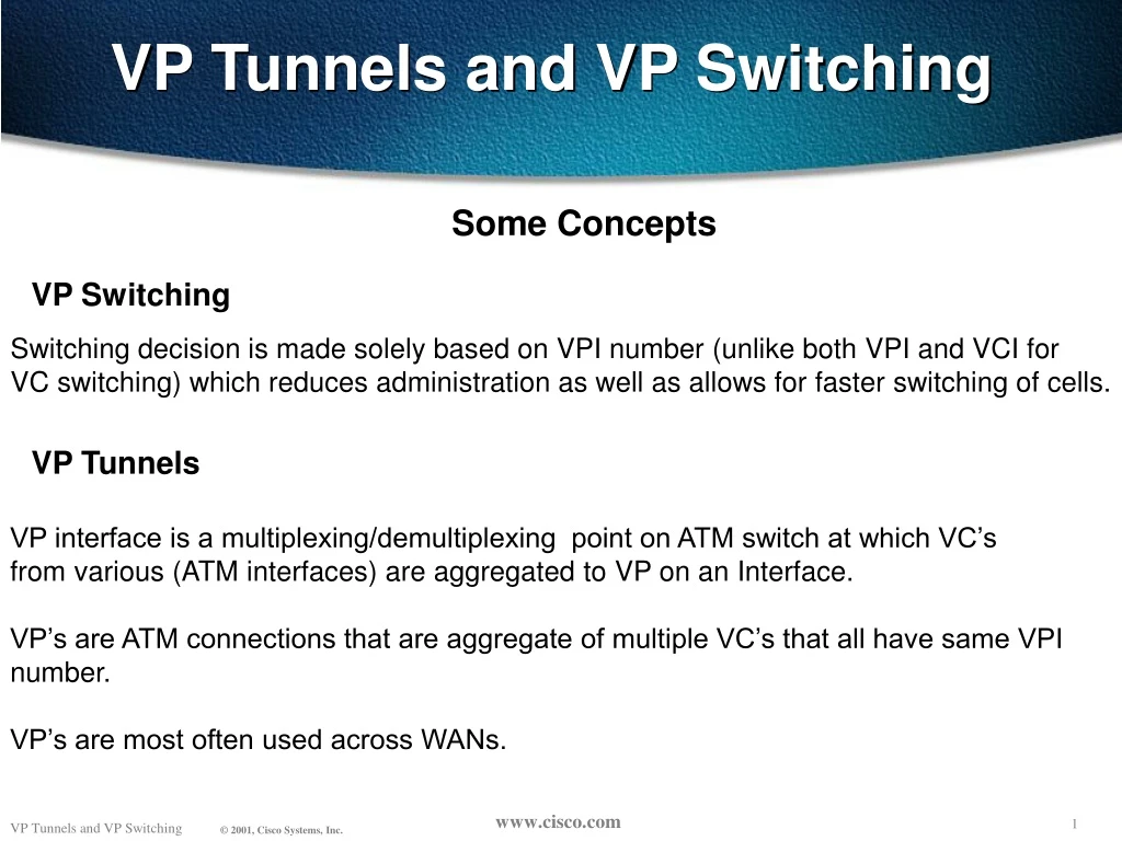
VP Tunnels and VP Switching Some Concepts VP Switching Switching decision is made solely based on VPI number (unlike both VPI and VCI for VC switching) which reduces administration as well as allows for faster switching of cells. VP Tunnels VP interface is a multiplexing/demultiplexing point on ATM switch at which VC’s from various (ATM interfaces) are aggregated to VP on an Interface. VP’s are ATM connections that are aggregate of multiple VC’s that all have same VPI number. VP’s are most often used across WANs.
VP VP VC TransmissionPath VP VP VC VP Tunnels and VP Switching There are 2 major type of ATM connections 1- VC (Virtual Channel): VC’s are uniquely identified on port of ATM switch by VPI and VCI number. 2- VP (Virtual Path): VP’s are uniquely identified on ATM port by VPI number on ATM port. VirtualPath ATM cells arriving on VC are switched based on both VPI and VCI number in cell header. On other hand ATM cells arriving on VP are Switched based on VPI number only. Configuration of ATM switch will determine If switch is supposed to be VC or VP switching For specific VPI/VCI pair or VPI respectively. VC VC
Port VPI/VCI Port VPI/VCI 1 2/100 4 7/110 1 2/110 3 1/50 2 5/110 4 7/100 VCI 100 Port 1 Port 3 VPI 2 VPI 1 VCI 50 VCI 110 VCI 100 Port 2 Port 4 VCI 110 VPI 5 VPI 7 VCI 110 VP Tunnels and VP Switching VC and VPSwitching OR • A cell is switch at VC or VP level. • VC Switching - Switch receive a cell with a configured VPI and VCI, it lookup its connection table to determine outgoing port (or ports) with new VPI/VCI value.
Atm5/1/0 Atm0/0/1 Atm0/0/0 Atm0/0/0 Atm0/0/1 Atm0/0/0 VP Tunnels and VP Switching Configuring VP Switching interface ATM5/1/0 no ip address no atm ilmi-keepalive ! interface ATM5/1/0.1 point-to-point ip address 1.1.1.1 255.255.255.0 pvc 10/20 encapsulation aal5snap ! interface ATM5/1/0.2 point-to-point ip address 2.1.1.1 255.255.255.0 pvc 10/30 encapsulation aal5snap ! interface ATM5/1/0.3 point-to-point ip address 3.1.1.1 255.255.255.0 pvc 11/40 interface ATM0/0/1 no ip address atm pvp 10 interface ATM0/0/0 10 atm pvp 11 interface ATM0/0/0 11 interface ATM0/0/1 no ip address atm pvp 10 interface ATM0/0/0 10 atm pvp 12 interface ATM0/0/0 11 interface ATM0/0/0 no ip address no atm ilmi-keepalive ! interface ATM0/0/0.1 point-to-point ip address 1.1.1.2 255.255.255.0 pvc 10/20 encapsulation aal5snap ! interface ATM0/0/0.2 point-to-point ip address 2.1.1.2 255.255.255.0 pvc 10/30 encapsulation aal5snap ! interface ATM0/0/0.3 point-to-point ip address 3.1.1.2 255.255.255.0 pvc 12/40 encapsulation aal5snap Check this out
VP Tunnels and VP Switching Show Commands for VP Switching Switch#sh atm vp Interface VPI Type X-Interface X-VPI Status ATM0/0/0 10 PVP ATM0/0/1 10 UP ATM0/0/0 11 PVP ATM0/0/1 12 UP ATM0/0/1 10 PVP ATM0/0/0 10 UP ATM0/0/1 12 PVP ATM0/0/0 11 UP Switch#sh atm vp traffi int atm0/0/0 Interface VPI Type rx-cell-cnts tx-cell-cnts ATM0/0/0 10 PVP 70 60 ATM0/0/0 11 PVP 94 90
VP Tunnels and VP Switching Switch#sh atm vp int atm0/0/0 10 Interface: ATM0/0/0, Type: oc3suni VPI = 10 Status: UP Time-since-last-status-change: 00:58:11 Connection-type: PVP Cast-type: point-to-point Cross-connect-interface: ATM0/0/1, Type: oc3suni Cross-connect-VPI = 10 Rx connection-traffic-table-index: 1 Rx service-category: UBR (Unspecified Bit Rate) Rx pcr-clp01: 7113539 Rx scr-clp01: none Rx mcr-clp01: none Rx cdvt: 1024 (from default for interface) Rx mbs: none Tx connection-traffic-table-index: 1 Tx service-category: UBR (Unspecified Bit Rate) Tx pcr-clp01: 7113539 Tx scr-clp01: none Tx mcr-clp01: none Tx cdvt: none Tx mbs: none Show Commands for VP Switching
VP Tunnels and VP Switching Three different types of VP Tunnels on Cisco Enterprise ATM Switches 1- Regular or Unshaped VP Tunnels 2- Shaped VP Tunnels 3- Hierarchical VP Tunnels
VP Tunnels and VP Switching Regular or Unshaped VP Tunnels VP tunnels on which there is no traffic shaping for any ATM service category. VP can be of any service category but can’t be shaped. VC’s in a tunnel have to be of same service category VP tunnel is.
Atm0/0/0 Atm0/0/0 Atm5/1/0 Atm0/0/1 Atm0/0/1 Atm0/0/0 VP Tunnels and VP Switching Configuring VP Tunnels for a Single Service Category WAN Tunnel Tunnel Public PVP Router 1 interface ATM5/1/0.1 point-to-point ip address 1.1.1.1 255.255.255.0 pvc 100/32 encapsulation aal5snap ! interface ATM5/1/0.2 point-to-point ip address 2.1.1.1 255.255.255.0 pvc 100/33 encapsulation aal5snap Router 2 interface ATM0/0/0.1 point-to-point ip address 1.1.1.2 255.255.255.0 pvc 100/32 encapsulation aal5snap ! interface ATM0/0/0.2 point-to-point ip address 2.1.1.2 255.255.255.0 pvc 100/40 encapsulation aal5snap ! Switch 1 interface ATM0/0/0 no ip address atm pvp 100 ! interface ATM0/0/0.100 point-to-point no ip directed-broadcast no atm ilmi-keepalive ! interface ATM0/0/1 no ip address no ip directed-broadcast logging event subif-link-status atm ilmi-keepalive atm svcc vci min 100 atm pvc 100 32 interface ATM0/0/0.100 100 32 atm pvc 100 33 interface ATM0/0/0.100 100 33 ! Switch 2 interface ATM0/0/0 no ip address atm pvp 100 ! interface ATM0/0/0.100 point-to-point ! interface ATM0/0/1 no ip address atm pvc 100 32 interface ATM0/0/0.100 100 32 atm pvc 100 40 interface ATM0/0/0.100 100 33 !
VP Tunnels and VP Switching Switch#sh atm vp int atm 0/0/0 100 Interface: ATM0/0/0, Type: oc3suni VPI = 100 Status: TUNNEL Time-since-last-status-change: 17:21:32 Connection-type: PVP Cast-type: point-to-point Rx cells: 49968, Tx cells: 50371 Rx connection-traffic-table-index: 1 Rx service-category: UBR (Unspecified Bit Rate) Rx pcr-clp01: 7113539 Rx scr-clp01: none Rx mcr-clp01: none Rx cdvt: 1024 (from default for interface) Rx mbs: none Tx connection-traffic-table-index: 1 Tx service-category: UBR (Unspecified Bit Rate) Tx pcr-clp01: 7113539 Tx scr-clp01: none Tx mcr-clp01: none Tx cdvt: none Tx mbs: none Show Commands for VP Tunnels
VP Tunnels and VP Switching Show Commands for VP Tunnels Switch#sh atm vp Interface VPI Type X-Interface X-VPI Status ATM0/0/0 100 PVP TUNNEL Switch#sh atm vp traffic int atm0/0/0 Interface VPI Type rx-cell-cnts tx-cell-cnts ATM0/0/0 100 PVP 49865 50271
Atm0/0/0 Atm0/0/0 Atm5/1/0 Atm0/0/1 Atm0/0/1 Atm0/0/0 VP Tunnels and VP Switching Configuring VP Tunnels for a Single Service Category WAN Router 1 interface ATM5/1/0.1 point-to-point ip address 1.1.1.1 255.255.255.0 pvc 100/32 vbr-nrt 50000 40000 100 encapsulation aal5snap ! ! interface ATM5/1/0.2 point-to-point ip address 2.1.1.1 255.255.255.0 pvc 100/33 vbr-nrt 10000 8000 100 encapsulation aal5snap ! Public PVP Switch 1 interface ATM0/0/0 no ip address atm pvp 100 rx-cttr 7 tx-cttr 7 ! interface ATM0/0/0.100 point-to-point no ip directed-broadcast no atm ilmi-keepalive ! interface ATM0/0/1 no ip address atm pvc 100 32 rx-cttr 8 tx-cttr 8 interface ATM0/0/0.100 100 32 atm pvc 100 33 rx-cttr 9 tx-cttr 9 interface ATM0/0/0.100 100 33 ! Router 2 interface ATM0/0/0.1 point-to-point ip address 1.1.1.2 255.255.255.0 pvc 100/32 vbr-nrt 50000 40000 100 encapsulation aal5snap ! interface ATM0/0/0.2 point-to-point ip address 2.1.1.2 255.255.255.0 pvc 100/40 vbr-nrt 10000 8000 100 encapsulation aal5snap Switch 2 interface ATM0/0/0 no ip address atm pvp 100 rx-cttr 7 tx-cttr 7 ! interface ATM0/0/0.100 point-to-point ! interface ATM0/0/1 no ip address atm pvc 100 32 rx-cttr 8 tx-cttr 8 interface ATM0/0/0.100 100 32 atm pvc 100 40 rx-cttr 9 tx-cttr 9 interface ATM0/0/0.100 100 33
VP Tunnels and VP Switching Switch c8510m-r2#sh atm vp int atm 0/0/0 100 Interface: ATM0/0/0, Type: oc3suni VPI = 100 Status: TUNNEL Time-since-last-status-change: 00:43:49 Connection-type: PVP Cast-type: point-to-point Rx connection-traffic-table-index: 7 Rx service-category: VBR-NRT (Non-Realtime Variable Bit Rate) Rx pcr-clp01: 100000 Rx scr-clp0 : 80000 Rx mcr-clp01: none Rx cdvt: 1024 (from default for interface) Rx mbs: 100 Tx connection-traffic-table-index: 7 Tx service-category: VBR-NRT (Non-Realtime Variable Bit Rate) Tx pcr-clp01: 100000 Tx scr-clp0 : 80000 Tx mcr-clp01: none Tx cdvt: none Tx mbs: 100 Show Commands
VP Tunnels and VP Switching Minimum Hardware/Software requirements and Type of VP Tunnel supported on Cisco equipment. 1- Unshaped VP Tunnel of any service category is supported on LS1010 (with eother FC-PCQ and FC-PFQ), Catalyst 8540-MSR, Catalyst 8510-MSR, 7500 series router with PA-A3 and 7200 series router with PA-A2 or PA-A3. Any 11.2, 11.3 or 12.0 IOS supports this feature . VC’s within unshaped tunnel have to be of same Service category that unshaped VP tunnel is. 2- Shaped VP Tunnel of CBR service category is supported on LS1010 with FC-PFQ, Catalyst 8510-MSR, Catalyst 8540-MSR, 7500 series router with PA-A3 and 7200 series router with PA-A2 or PA-A3. All VC’s Within CBR VP Tunnel have to be of same service category. 2.1- Shaped VP Tunnels are first supported in 11.2(8.0.1)FWA4 vs of IOS 11.1 and WA3 release trains do not Support shaped VP Tunnels. 2.2- For software vs after 11.3(0.8)TWA4 it is supported for service category of VC’swithin shaped tunnel To be on CBR. 2.3- For earlier software vs that do support shaped VP tunnel VC’s within shaped CBR tunnel have to be of CBR service category. 3- Hierarchical VP Tunnels of CBR service category are supported on LS1010 with FC-PFQ, Catalyst 8510-MSR and Catalyst 8540-MSR. Minimum software requirement is W5 train of IOS.
VP Tunnels and VP Switching ??? If the VP Service Provider is Policing, the connection will most likely experience cell drops in the Service Provider network. Q: How to overcome this? A: Configure Shaped VP Tunnels.
VP Tunnels and VP Switching Shaped VP Tunnels VP Tunnels that are traffic shaped. They are defined only for CBR service category on Cisco Enterprise ATM Switches. All VC’s within single VP Tunnel must be same service category. The overall output of this VP Tunnel is rate-limited by hardware to the PCR of the tunnel.
WAN Atm0/0/0 Atm0/0/0 Public PVP Atm5/1/0 Atm0/0/1 Atm0/0/1 Atm0/0/0 VP Tunnels and VP Switching Configuring Shaped VP Tunnels Switch 1 atm connection-traffic-table-row index 10 cbr pcr 8000 atm connection-traffic-table-row index 20 vbr-nrt pcr 7000 scr0 4000 mbs 100 atm connection-traffic-table-row index 30 ubr pcr 8000 atm connection-traffic-table-row index 40 abr pcr 8000 mcr 0 ! interface ATM0/0/0 no ip address atm pvp 100 shaped rx-cttr 10 tx-cttr 10 atm pvp 110 shaped rx-cttr 10 tx-cttr 10 atm pvp 120 shaped rx-cttr 10 tx-cttr 10 ! interface ATM0/0/0.100 point-to-point atm cac service-category cbr deny atm cac service-category vbr-nrt permit ! interface ATM0/0/0.110 point-to-point atm cac service-category cbr deny atm cac service-category ubr permit ! interface ATM0/0/0.120 point-to-point atm cac service-category cbr deny atm cac service-category abr permit ! interface ATM0/0/1 no ip address atm pvc 100 32 rx-cttr 20 tx-cttr 20 interface ATM0/0/0.100 100 32 atm pvc 110 40 rx-cttr 30 tx-cttr 30 interface ATM0/0/0.110 110 40 atm pvc 120 50 rx-cttr 40 tx-cttr 40 interface ATM0/0/0.120 120 50 Router 1 interface ATM5/1/0.1 point-to-point ip address 1.1.1.1 255.255.255.0 pvc 100/32 vbr-nrt 7000 4000 100 encapsulation aal5snap ! interface ATM5/1/0.2 point-to-point ip address 2.1.1.1 255.255.255.0 pvc 110/40 ubr 8000 ! interface ATM5/1/0.3 point-to-point ip address 3.1.1.1 255.255.255.0 pvc 120/50 abr 8000 5000
VP Tunnels and VP Switching Configuring Shaped VP Tunnels Switch 2 atm connection-traffic-table-row index 10 cbr pcr 8000 atm connection-traffic-table-row index 20 vbr-nrt pcr 7000 scr0 4000 mbs 100 atm connection-traffic-table-row index 30 ubr pcr 8000 atm connection-traffic-table-row index 40 abr pcr 8000 mcr 0 ! interface ATM0/0/0 no ip address atm pvp 100 shaped rx-cttr 10 tx-cttr 10 atm pvp 110 shaped rx-cttr 10 tx-cttr 10 atm pvp 120 shaped rx-cttr 10 tx-cttr 10 ! interface ATM0/0/0.100 point-to-point atm cac service-category cbr deny atm cac service-category vbr-nrt permit ! interface ATM0/0/0.110 point-to-point atm cac service-category cbr deny atm cac service-category ubr permit ! interface ATM0/0/0.120 point-to-point no atm ilmi-keepalive atm cac service-category cbr deny atm cac service-category abr permit ! interface ATM0/0/1 no ip address atm pvc 100 32 rx-cttr 20 tx-cttr 20 interface ATM0/0/0.100 100 32 atm pvc 110 40 rx-cttr 30 tx-cttr 30 interface ATM0/0/0.110 110 40 atm pvc 120 50 rx-cttr 40 tx-cttr 40 interface ATM0/0/0.120 120 50 Router 2 interface ATM0/0/0.1 point-to-point ip address 1.1.1.2 255.255.255.0 pvc 100/32 vbr-nrt 7000 4000 100 encapsulation aal5snap ! interface ATM0/0/0.2 point-to-point ip address 2.1.1.2 255.255.255.0 pvc 110/40 ubr 8000 ! interface ATM0/0/0.3 point-to-point ip address 3.1.1.2 255.255.255.0 pvc 120/50 abr 8000 5000
VP Tunnels and VP Switching Show Commands for Shaped VP Tunnels Switch#sh atm vp int atm0/0/0 Interface VPI Type X-Interface X-VPI Status ATM0/0/0 100 PVP SHAPED TUNNEL ATM0/0/0 110 PVP SHAPED TUNNEL ATM0/0/0 120 PVP SHAPED TUNNEL Switch#sh atm vp traffic int atm0/0/0 Interface VPI Type rx-cell-cnts tx-cell-cnts ATM0/0/0 100 PVP 1438 1446 ATM0/0/0 110 PVP 1374 1384 ATM0/0/0 120 PVP 755 772
VP Tunnels and VP Switching Show Commands for Shaped VP Tunnels Switch#sh atm int atm0/0/0.110 Interface: ATM0/0/0.110 Port-type: vp tunnel IF Status: UP Admin Status: up
VP Tunnels and VP Switching Restrictions for Shaped VP tunnels 1- LS1010 with FC-PFQ and Catalyst 8510-MSR support maximum of 2x64=128 shaped VP Tunnels:64 shaped VP Tunnels are supported on x/0/y numbered ports and 64 on x/1/y numbered ports. 2- Catalyst 8540-MSR supports maximum of 8x64=512 shaped VP tunnels: maximum of 64 shaped VP tunnels Can be defined on each of the following interface groups: (0/0/x, 1/0/x), (0/1/x, 1/1/x), (2/0/x, 3/0/x), (2/1/x, 3/1/x), (9/0/x, 10/0/x), (9/1/x, 10/1/x), (11/0/x, 12/0/x), and (11/1/x, 12/1/x). 3- The bandwidth of the shaped VP tunnel is shared by the active VC’s inside the tunnel in strict round-robin (RR) fashion. 4- Shaped VP tunnels do not support merged VC’s for tag switching. 5- UBR+ and ABR VC’s with non-zero MCR are not allowed on a shaped VP tunnel interface. 6- A maximum of 128 VC’s can transit s shaped VP tunnel interface.
VP Tunnels and VP Switching ??? Q: What if I have more than 1 service category and cann’t buy more than 1 VP Tunnel? A: Configure Hierarchical VP Tunnel
VP Tunnels and VP Switching Hierarchical VP Tunnels VP Tunnels that are traffic shaped and support VC’s of multiple service categories to co-exist in tunnel at the same time.
WAN Atm0/0/0 Atm2/1/0 Public PVP Atm5/1/0 Atm0/0/1 Atm2/1/1 Atm0/0/0 VP Tunnels and VP Switching Configuring Hierarchical VP Tunnels for Multiple Services Categories Switch 1 atm hierarchical-tunnel atm connection-traffic-table-row index 20 vbr-nrt pcr 7000 scr0 4000 mbs 100 atm connection-traffic-table-row index 30 ubr pcr 8000 atm connection-traffic-table-row index 40 abr pcr 8000 mcr 0 atm connection-traffic-table-row index 50 cbr pcr 50000 ! interface ATM0/0/0 no ip address no ip directed-broadcast logging event subif-link-status atm pvp 100 hierarchical rx-cttr 50 tx-cttr 50 ! interface ATM0/0/0.100 point-to-point no ip directed-broadcast no atm ilmi-keepalive ! interface ATM0/0/1 no ip address no ip directed-broadcast logging event subif-link-status atm pvc 100 32 rx-cttr 20 tx-cttr 20 interface ATM0/0/0.100 100 32 atm pvc 100 40 rx-cttr 30 tx-cttr 30 interface ATM0/0/0.100 100 40 atm pvc 100 50 rx-cttr 40 tx-cttr 40 interface ATM0/0/0.100 100 50 Router 1 interface ATM5/1/0.1 point-to-point ip address 1.1.1.1 255.255.255.0 pvc 100/32 vbr-nrt 7000 4000 100 encapsulation aal5snap ! interface ATM5/1/0.2 point-to-point ip address 2.1.1.1 255.255.255.0 pvc 100/40 ubr 8000 encapsulation aal5snap ! interface ATM5/1/0.3 point-to-point ip address 3.1.1.1 255.255.255.0 pvc 100/50 abr 8000 5000 encapsulation aal5snap
VP Tunnels and VP Switching Configuring Hierarchical VP Tunnels for Multiple Services Categories Switch 2 atm hierarchical-tunnel atm connection-traffic-table-row index 20 vbr-nrt pcr 7000 scr0 4000 mbs 100 atm connection-traffic-table-row index 30 ubr pcr 8000 atm connection-traffic-table-row index 40 abr pcr 8000 mcr 0 atm connection-traffic-table-row index 50 cbr pcr 50000 ! interface ATM2/1/0 no ip address atm pvp 100 hierarchical rx-cttr 50 tx-cttr 50 ! interface ATM2/1/0.100 point-to-point ! interface ATM2/1/1 no ip address atm pvc 100 32 rx-cttr 20 tx-cttr 20 interface ATM2/1/0.100 100 32 atm pvc 100 40 rx-cttr 30 tx-cttr 30 interface ATM2/1/0.100 100 40 atm pvc 100 50 rx-cttr 40 tx-cttr 40 interface ATM2/1/0.100 100 50 Router 2 interface ATM0/0/0.1 point-to-point ip address 1.1.1.2 255.255.255.0 pvc 100/32 vbr-nrt 7000 4000 100 encapsulation aal5snap ! interface ATM0/0/0.2 point-to-point ip address 2.1.1.2 255.255.255.0 pvc 100/40 ubr 8000 encapsulation aal5snap ! interface ATM0/0/0.3 point-to-point ip address 3.1.1.2 255.255.255.0 pvc 100/50 abr 8000 5000 encapsulation aal5snap
VP Tunnels and VP Switching Show Commands for Hierarchical VP Tunnels Switch#sh atm vp Interface VPI Type X-Interface X-VPI Status ATM2/1/0 100 PVP HIE. TUNNEL Switch#sh atm resource Resource configuration: Sustained-cell-rate-margin-factor 1% Abr-mode: EFCI Hierarchical Scheduling Mode : enabled *****TRUNCATED****** Switch#sh atm vp traffic int atm 2/1/0 100 Interface VPI Type rx-cell-cnts tx-cell-cnts ATM2/1/0 100 PVP 2451 2470
VP Tunnels and VP Switching Show Commands for Hierarchical VP Tunnels Switch#sh atm vp int atm2/1/0 100 Interface: ATM2/1/0, Type: oc3suni VPI = 100 Status: HIE. TUNNEL Time-since-last-status-change: 00:49:16 Connection-type: PVP Cast-type: point-to-point Rx cells: 2214, Tx cells: 2234 Rx connection-traffic-table-index: 50 Rx service-category: CBR (Constant Bit Rate) Tx connection-traffic-table-index: 50 Tx service-category: CBR (Constant Bit Rate) Tx pcr-clp01: 50000 Tx scr-clp01: none Tx mcr-clp01: none Tx cdvt: none Tx mbs: none
VP Tunnels and VP Switching Restriction for Hierarchical VP Tunnels 1- LS1010 with FC-PFQ, Catalyst 5500 with ASP and FC-PFQ and Catalyst 8510-MSR support maximum of 62 hierarchical VP Tunnels. 2- Hierarchical VP Tunnels can only be defined on ports in slots 0 and 3 on LS1010 and Catalyst 8510-MSR. Hierarchical VP Tunnels can be defined in slots 9 and 11 on Catalyst 5500 with ASP and FC-PFQ. 3- LS1010 equiped with FC-PFQ and ASP-B supports maximum of 30 hierarchical VP tunnels on ports 0/0/z And 3/0/z combined, and maximum of 32 on ports 0/1/z and 3/1/z combined. Use “sh hardware” command to Find out type of ASP and feature card. 4- LS1010 equiped with FC-PFQ and ASP-C as well as Catalyst 8510-MSR support maximum of 30 Hierarchical VP tunnels on ports 0/y/z and maximum of 32 on ports 3/y/z. 5- On Catalyst 5500 with ASP and FC-PFQ Maximum of 30 hierarchical VP tunnels can be defined on ports 9/0/z and11/0/7 combined. Maximum of 32 hierarchical VP tunnels can be defined on ports 9/1/z and 11/1/z Combined. 6- On Catalyst 8540-MSR hierarchical VP tunnels can be defined on slots 0,2,9 and 11.
VP Tunnels and VP Switching Restriction for Hierarchical VP Tunnels 7- Maximum number of hierarchical VP Tunnels varies between 120 and 240 depending on type of PAM’s Used. If all the ports are Super PAM’s (full with modules) the maximum number of VP tunnels supported Is 240. If all the ports installed are Supper Cam’s with LS1010 PAM’s maximum number of hierarchical VP tunnels is 120. 8- Hierarchical VP tunnels can not co-exist with any other type of connection (VC’s, VP’s, Tag VC’s regular Or shaped VP tunnels etc.) on the same physical interface. So, the only type of connection that can coexist With hierarchical VP tunnel on same physical interface are additional hierarchical VP tunnels and well Known VC’s (signaling 0/5, PNNI, 0/18, ILMI 0/16 etc.). 9- Hierarchical VP Tunnels can support only ATM Forum VC’s or only Tag VC’s, but not both at the same time. 10- When doing OIR (on line insertion and removal) of PAM that has hierarchical VP tunnels configured For its ports, configuration of hierarchical tunnel will be preserved. So if same PAM is inserted back In hierarchical VP Tunnel will automaticly be active. However,if different type of PAM is to be inserted It is strongly recommended that any configured hierarchical VP Tunnel (on port about to be removed) be Deleted prior to physical removal of PAM.
VP Tunnels and VP Switching Some Acronyms VP: virtual path VC: virtual channel VPI: virtual path identifier VCI: virtual channel identifier ABR: available bit rate CBR: constant bit rate UBR: unspecified bit rate VBR-nrt: variable bit rate – no real time VBR-rt: variable bit rate – real time PCR: peak cell rate SCR: sustained cell rate MBS: maximum burst size FC-PFQ: feature card- per flow queueing