ELECTRICAL CIRCUITS
Learn the fundamentals of electrical circuits, including Ohm's Law, voltage, resistance, and current. Discover the concepts of series and parallel circuits, and explore the principles of measuring current and voltage. Understand Kirchoff's Laws and the characteristics of circuit components.

ELECTRICAL CIRCUITS
E N D
Presentation Transcript
ELECTRICAL CIRCUITS All you need to be an inventor is a good imagination and a pile of junk. -Thomas Edison
Ohm’s Law I = V / R I = Current (Amperes) (amps) V = Voltage (Volts) R = Resistance (ohms) Georg Simon Ohm (1787-1854)
How you should be thinking about electric circuits: Voltage: a force that pushes the current through the circuit (in this picture it would be equivalent to gravity)
How you should be thinking about electric circuits: Resistance: friction that impedes flow of current through the circuit (rocks in the river)
How you should be thinking about electric circuits: Current: the actual “substance” that is flowing through the wires of the circuit (electrons!)
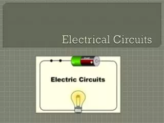
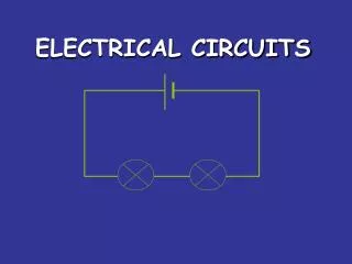
circuit diagram Scientists usually draw electric circuits using symbols; cell lamp switch wires
Simple Circuits • Series circuit • All in a row • 1 path for electricity • 1 light goes out and the circuit is broken • Parallel circuit • Many paths for electricity • 1 light goes out and the others stay on
1 2 3 The current decreases because the resistance increases. Ohm’s Law says that I=V/R. The voltage in the system is constant, resistance increases.
PARALLEL CIRCUIT • Place two bulbs in parallel. What do you notice about the brightness of the bulbs? • Add a third light bulb in the circuit. What do you notice about the brightness of the bulbs? • Remove the middle bulb from the circuit. What happened?
measuring current Electric current is measured in amps(A) using an ammeter connected in series in the circuit. A
measuring current This is how we draw an ammeter in a circuit. A A PARALLEL CIRCUIT SERIES CIRCUIT
measuring voltage The ‘electrical push’ which the cell gives to the current is called the voltage. It is measured in volts (V) on a voltmeter V
measuring voltage This is how we draw a voltmeter in a circuit. V V SERIES CIRCUIT PARALLEL CIRCUIT
OHM’s LAW • Measure the current and voltage across each circuit. • Use Ohm’s Law to compute resistance Series Circuit Parallel Circuit
measuring current SERIES CIRCUIT 2A • current is the same • at all points in the • circuit. 2A 2A PARALLEL CIRCUIT 2A 2A • current is shared • between the • components 1A 1A
fill in the missing ammeter readings. ? 3A 3A ? 4A ? 1A ? 4A 4A 1A ? 1A
The circuit is no longer complete, therefore current can not flow The voltage decreases because the current is decreased and the resistance increases.
The current remains the same. The total resistance drops in a parallel circuit as more bulbs are added The current increases.
Series and Parallel Circuits • Series Circuits • only one end of each component is connected • e.g. Christmas tree lights • Parallel Circuits • both ends of a component are connected • e.g. household lighting
copy the following circuits and fill in the missing ammeter readings. ? 3A 3A ? 4A ? 1A ? 4A 4A 1A ? 1A
measuring voltage Different cells produce different voltages. The bigger the voltage supplied by the cell, the bigger the current. Unlike an ammeter, a voltmeter is connected across the components Scientist usually use the term Potential Difference (pd) when they talk about voltage.
measuring voltage V V V V
series circuit • voltage is shared between the components 3V 1.5V 1.5V
parallel circuit • voltage is the same in all parts of the circuit. 3V 3V 3V
measuring current & voltage copy the following circuits on the next two slides. complete the missing current and voltage readings. remember the rules for current and voltage in series and parallel circuits.
measuring current & voltage a) 6V 4A A V V A
measuring current & voltage b) 6V 4A A V A V A
answers a) b) 6V 4A 6V 4A 6V 4A 4A 2A 3V 3V 4A 6V 2A
Voltage, Current, and Power • One Volt is a Joule per Coulomb (J/C) • One Amp of current is one Coulomb per second (6.24 x10^18 electrons/second). • If I have one volt (J/C) and one amp (C/s), then multiplying gives Joules per second (J/s) • this is power: J/s = Watts • So the formula for electrical power is just: • More work is done per unit time the higher the voltage and/or the higher the current P = VI: power = voltage current
Kirchoff’s Laws • These laws add up to nothing! Yet they completely characterize circuit behavior. • Kirchoff’s Voltage Law (KVL) - The sum of voltages taken around any loop is zero. • The start and end points are identical; consequently there is no potential difference between them. • Kirchoff’s Current Law (KCL) – The sum of currents entering any node is zero. • A consequence of the law of conservation of charge.
Circuit components • Active vs. Passive components • Active ones may generate electrical power. • Passive ones may store but not generate power. • Lumped vs. Distributed Constants • Distributed constant components account for propagation times through the circuit branches. • Lumped constant components ignore these propagation times. Appropriate for circuits small relative to signal wavelengths. • Linear, time invariant (LTI) components are those with constant component values.
Active circuit components • Conservation of energy: active components must get their power from somewhere! • From non-electrical sources • Batteries (chemical) • Dynamos (mechanical) • Transducers in general (light, sound, etc.) • From other electrical sources • Power supplies • Power transformers • Amplifiers
Passive lumped constants • Classical LTI • Resistors are AC/DC components. • Inductors are AC components (DC short circuit). • Capacitors are AC components (DC open circuit). • Other components • Rectifier diodes. • Three or more terminal devices, e.g. transistors. • Transformers.
DC circuits • The basic LTI component is the Resistor • Customarily represented by R. • The SI unit is the Ohm []. • Ohm’s Law: V = I R Ohm’s and Kirchoff’s laws completely prescribe the behavior of any DC circuit comprising LTI components.
AC circuits -- Components • Basic LTI components • Resistor, R, [] (Ohms) • Inductor, L, [H] (Henrys) • Capacitor, C, [F] (Farads) • Frequency • Repetition rate, f, [Hz] (Hertz) • Angular, = 2f, [1/s] (radians/sec)
AC Components: Inductors • Current in an inductor generates a magnetic field, B = K1 I • Changes in the field induce an inductive voltage. V = K2 (dB/dt) • The instantaneous voltage is V = L(dI/dt), where L = K1K2. This is the time domain behavior of an inductor.
AC Components: Capacitors • Charge in a capacitor produces an electric field E, and thus a proportional voltage, Q = C V, Where C is the capacitance. • The charge on the capacitor changes according to I = (dQ/dt). • The instantaneous current is therefore I = C(dV/dt). This is the time domain behavior of a capacitor.
AC circuits -- Impedance • Impedance and Ohm’s Law for AC: • Impedance is Z = R + jX, where j = -1, and X is the reactance in []. • Ohm’s AC Law in s domain: v = i Z • Resistance R dissipates power as heat. • Reactance X stores and returns power. • Inductors have positive reactance Xl=L • Capacitors have negative reactance Xc=-1/C
Impedance shortcuts • The impedance of components connected in series is the complex sum of their impedances. • The impedance of components connected in parallel is the reciprocal of the complex sum of their reciprocal impedances.
Methods of Circuit Analysis • Mesh Analysis • Nodal Analysis
Mesh Analysis • Kirchhoff’s Voltage Law (KVL) forms the basis of mesh analysis. • This technique is applicable to • Basic circuit • Circuit with dependent source • Circuit with current source • Case 1: Current source at the outer most boundary (known as mesh current) • Case 2: Current source in between two loops (known as supermesh)
Step to determine Mesh Current • Assign mesh currents I1, I2…, In to the n meshes • Apply KVL to each of n meshes. Use Ohm’s Law to express voltages in terms of mesh currents. • Solve the resulting n simultaneous equation to get the mesh current,
Example 10.3For the circuit below, find Io using mesh analysis
Solution Applying KVL to Mesh 1 …(1) Mesh 2 …(2) Substitute (I3=5) into meshes (1) and (2) …(3) …(4)
Solution Put equation (3) and (4) in matrix form Find determinant for the matrix (Cramer’s Rule)