Download
1 / 48
480 likes | 494 Vues
Learn about the instruction set of the 8086 microprocessor and the different addressing modes. Explore the basic instructions, instruction formats, and operation codes. Gain knowledge in immediate and direct addressing modes.

E N D
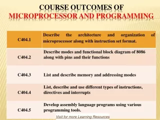
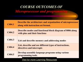
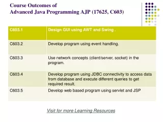
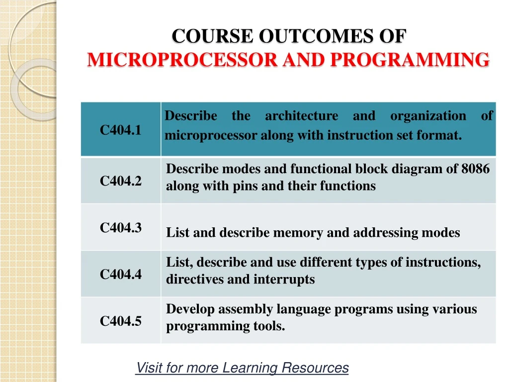
COURSE OUTCOMES OF MICROPROCESSOR AND PROGRAMMING Visit for more Learning Resources
Instruction set of 8086 microprocessor CHAPTER 3
Basic of 8086 • It has 32 addressing modes. • It has 1 million instruction. From that 117 is basic instruction. • The instruction length is not fixed • The 8086 provides 8 bit and 16 bit instruction
Instruction format • A machine language instruction format has more than one number of field • 1st field is called operation code field or op-code indicates the type of operation to be performed by the CPU. • 2nd field is called operand field indicates data field on which the operation by instruction op-code. • It has 6 general format of instruction in 8086 instruction set. • Length of an instruction may vary from 1 byte to 6 byte
Operation code field or op-code Operand field i.e data field Operation code field or op-code • op-code byte:= • - This byte is always present in each instruction . • This indicates the operation to be carried out by 8086 • Format of op-code byte:= Op-code D W
Op-code field indicates the operation to be carried out D D bit indicates whether the register is a source /distinction register. D=0 indicates that the register is source register. D=1 indicates that the register the distinction register. W word or byte .This bit is present if byte or word option is available for that instruction . w bit indicates whether the instruction is a byte or word instruction. W=0 indicates instruction that operates on bytes. W=1 indicates instruction that operates on words
One byte instruction • This format is only 1 byte long and may have implicit data or register operands. • The least 3 bits of op-code are used to specify the register operand. • Otherwise all the 8 bit form an op-code and the operand are implied.
Register to register • This format is 2 byte long • 1st byte of code consist of operation code of instruction and width of the operand specified by w bit. • 2nd byte of code consist of register & R/M field. • REG indicates the name of the register i.e source or destination. • R/M indicates source or destination operand is located in register
1st Byte 6 bit 1 bit Op-Code W 2nd Byte 1 bit 1 bit 3 bit 3 bit 1 1 REG R/M
Register to/memory with no displacement • This format is also 2 byte long • 1st byte of code same as that of register to register format • 2nd byte of code consist of MOD , REG,R/M field. • MOD indicates the displacement is present or not .if present then it is 8bit or 16 bit.
1st Byte 6 bit 1 bit Op-Code W 2nd Byte 3 bit 2 bit 3 bit MOD REG R/M
Register to/from memory with displacement • This type of instruction format contain on or two additional bytes for displacement along with 2 byte format of register to/from memory without displacement
1st Byte 6 bit 2 bit Op-Code W 2nd Byte 2 bit 3 bit 3 bit MOD REG R/M 4th Byte 3rd Byte 8 bit 8 bit Lower Byte displacement Higher Byte displacement
Immediate operand to register • In this format first byte as well as the 3 bits from the second byte which are used for REG field in case of register –to-register are used for op-code.
1st Byte 8 bit OPCODE 2nd Byte 1 bit 3 bit 3 bit 1 bit REG R/M 1 1 4th Byte 3rd Byte 8 bit 8 bit Lower Byte DATA Higher byte DATA
Immediate operand to memory with 16 bit displacement • This type of instruction format requires 5 or 6 byte for coding • The first two byte contain the information of OPCODE ,MOD ,R/M field
Addressing modes of 8086 • Addressing modes indicates a way of locating data • Depending upon the data type used in the instruction & memory addressing modes any instruction may belong to one or more addressing modes • According to the flow of instruction execution instruction categorized as 1) sequential control flow instruction 2) control transfer instruction
Sequential control flow instruction are the instruction which after execution ,transfer the control to the next instruction appearing immediately after it in the program e.g the arithmetic , logical , data transfer and process control instruction. • The control transfer instruction transfer the control predefined address of the memory somehow specified in the instruction after their execution e.g : INT ,CALL , JMP ,RET etc
Immediate addressing modes • In this mode the immediate data is the part of the instruction and appear in the form of byte • So immediate data may be 8 bit or 16 bit in length. • Immediate data can be accessed quickly as they are available in an instruction queue. Hence no extra bus cycle is required. • E.g: Mov AL,46H = AL is loaded with 8 bit immediate data 46H • Mov BX,1234H=BX is loaded with 16 bit immediate data 1234H.
Direct addressing mode • In this mode a 16 bit memory address of operand is directly specified in the instruction as a part of it. • The offset of displacement may be 8 bit or 16 bit which follow the instruction op-code • The physical address is calculated by adding the offset to the base segment register i.e cs ,ds, es, ss • E.g: Mov AL,[3000H]= AL will be loaded with the content of memory location whose offset is 3000H
Register addressing mode • In this mode the data is stored in a register and it is referred using the particular register. • Register is source or destination. • The instruction of this mode is compact and faster in execution • Register are 8bit or 16 bit • E.g: mov AX,CX= copies the contents of CX to AX
Register indirect addressing mode • In this mode ,the address of the memory location that contain data is determined in an indirect way ,using offset register such as BX ,SI ,DI register. • The default segment register is either DS , ES • If BP is used then SS is default segment register. • E.g: MOV AX,[BX] = copies the content of memory location whose offset is in BX register
Register relative addressing mode • In this mode the data is available at an effective formed by adding 8 bits or 16 bits displacement with contents of any one of the register such as BX,BP,SI or DI in the default DS and ES segment. • E.g:= MOV AX,50[BX]= copies the word from memory location whose offset will be calculated by adding the content 50 with the content of BX register
Base indexed addressing mode • In this mode the effective address of data is formed by adding the content of a base register BX or BP to the content of an index register SI or DI with default segment DS and ES • E.g: MOV AX,[BX][SI]= copies the word from memory location whose offset is calculated by adding the content of BX with content of SI
Relative base indexed addressing mode • In this mode the effective address of data is calculated by adding the 8 bit or 16 bit displacement with the sum of base register BX or BP and SI or DI register in the default segment DS and Es • E.g: MOV AX,60[BX][SI]=copies word from memory location whose offset is calculated by adding the 60H with the content of BX and SI
Instruction set of 8086 • Data transfer /copy instructions • Arithmetic &logical instructions • Brach instructions • Loop instructions • Machine control instructions • Flag manipulation instructions • Shift and rotate instructions • String instructions
Data transfer/copy instructions • These types of instruction used to transfer data from source operand to destination operand. • All the store,move,load,exchange,input & output instruction come in this category
Mov destination, source • Syntax: Mov destination,source • Operation: destination source • The mov instruction copies a word(16 bit) or byte(8 bit) of data from a specified source to a specified destination • The destination can be a register or a memory location. • The source can be a register or memory location or immediate number. • The source &destination both can not be memory location at one time. • The source &destination in a mov instruction must be of type byte or they must both be of type word. It can not affect any flag. • E.g: mov cx,037H= put an immediate no 037h in cx mov ax,bx = copy contents of bx into ax
PUSH-push to stack • Syntax: PUSH source • Operation: SPSP-2 SS:[SP]higher byte of source SS:[SP-1]lower byte of source -The push instruction decrements the stack pointer by 2 & copies a word from source to the location in the stack segment where the stack pointer pointes -The source of the word can be a general-purpose register or memory -out of 2 decremented stack address the higher byte occupies the higher address & the lower byte occupies the lower address. e.g: PUSH BX= decrement sp by 2 ,copy BX to stack i.e content of BH register to higher address of stack & BL register to lower address of stack
POP-pop from stack • Syntax: pop destination • Operation: Lower byte of destinationSS:[SP] Higher byte of destinationSS:[SP+1] SPSP+2 • The pop instruction copies a word from stack location pointed by the stack pointer to a destination specified in the instruction. • The destination can be a general-purpose register,segment register or memory location
The data in the stack is not changed .After the word is copied to the specified destination,the stack pointer is automatically incremented by 2 to point the next word on the stack • E.g: • POP DX= copy a word from top of stack to DX, sp=sp+2 i.e content of [sp] to • DL register and content of [sp+1] to DH regsiter. • 2) POP DS = copy a word from top of the stack to DS register sp=sp+2 • 3) POP [8000] = copy a word from top of stack to memory loction 8000h and 8001h
XCHG-Exchange • Syntax: XCHG destination,source • Operation: destination ,source • This instruction exchanges the contents of a register with the contents of another register • The instruction can not directly exchange the contents of two memory location. • A memory location can be specified as the source or destination by any of 24 addressing modes • The source and destination both be word or byte • The segment register cannot be used in the instruction. • E.g: XCHG AX,BX= exchange the word in AX with word in BX XCHG BL,CH= exchange the byte in BL with byte in CH
IN-input data from a port • Syntax: IN accumulator,port • Operation: AL [port address] for byte AL[port address] AH[port address +1] for word -The IN instruction copies data from a port to destination which may be AL or AX The address of the port can be specified in the instruction directly or indirectly.
For the fixed port type the 8 bit address of a port is specified directly in the instruction • For variable port type the 16 bit address of a port is specified in DX register only. • DX register must always be loaded with the 16 bit port address before the IN instruction • E.g: • IN fixed port type: • IN AL,80H= Input a byte from port whose address is 80H • IN AX,80H= Input a word from port whose address is 80H • In variable port type: • MOV DX,8000H= initalize DX to point port with port address • IN AL,DX= input a byte from 8 bit port whose address is in DX to AL
OUT- output data to a port • Syntax: OUT port,accumulator • Operation: [port]AL for byte [port+1]AH for word • This instruction is used for writing to an output port. • The OUT instruction copies a byte from AL or from AX to specified port • The address of the port is specified in the instruction directly or indirectly
-For the fixed port type the 8 bit address of a port is specified directly in the instruction. • For variable port type the 16 bit address of a port is specified in DX register • DX register must always be loaded with the 16 bit port address before the OUT instruction. • E.g: 1) OUT AX,AL = copy the content of AL to port 80H • 2) MOV DX, 6000H= initalize DX with 16 bit port address • 3) OUT DX,AL= copy the contents of AL to port.
LEA-load effective address • Syntax: LEA register ,source • Operation: 16 bit registereffective address of memory location. -this instruction determines the offset of the variable or memory location names as the source and loads this offset in the specified 16 bit register. E.g: LEA BX,ARRAY= load BX with the offset of variable ARRAY.
LDS/LES-load register & DS/ES with words from memory • Syntax: LDS/LES register,memory address of first word. • Operation: For LDS: 16 bit register—[memory address] DS—[memory address+2] For LES: 16 bit register—[memory address] ES– [memory address +]
This instruction loads new values into specified register & add into DS/ES register from four successive memory location. • It then copies a word from next two consecutive memory location into the DS register. • E.g: • LDS BX,[1234H]= copy the contents of memory location 1234H in BL, contents of 1235H to BH and the content of 1236H &1237H in ES register.
LAHF-copy low byte of flag register to AH • Syntax: LAHF • Operation: AHlower byte of flag register • This instruction loads the AH register with the lower byte of the flag register. • This instruction may be used to observe the status of all the condition flags • The lower byte of 8086 flag register is same as the flag byte of the 8085
SAHF-store AH register to lower byte of flag register • Syntax: SAHF • Operation: lower byte of flag registerAH • This instruction copies the contents of AH register to the lower byte of 8086 flag register • This instruction set or reset the condition code flag in a lower byte of the flag register depending upon bit position in AH • If a bit in AH is 1 the flag corrpossponding to bit position is set else reset
PUSHF • This instruction decrements the stack pointer by two and copies the word in the flag register to the memory location pointed by the stack register • E.g: PUSHF
POPF • This instruction cpoies a word from the memory location at the top of stack to the flag register and incrment stack pointer by two • E.g: POPF