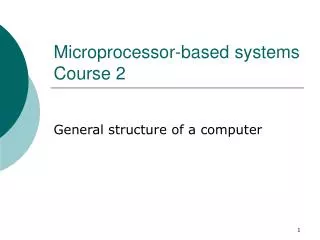
Microprocessor-based systems Course 2
Microprocessor-based systems Course 2. General structure of a computer. M. Data and program input. DE. DI. Data output. CU. ALU. CPU=CU+ALU Central Processing Unit. Components of a computer system. Classic computer model (J. von Neumann) Control unit (CU)

Microprocessor-based systems Course 2
E N D
Presentation Transcript
Microprocessor-based systemsCourse 2 General structure of a computer
M Data and program input DE DI Data output CU ALU CPU=CU+ALU Central Processing Unit Components of a computer system • Classic computer model (J. von Neumann) • Control unit (CU) • Arithmetical and logical unit (ALU) • Memory (M) • Input device(s) (ID) • Output device(s) (OD)
Memory Memory μP I/O Interface I/O Interface I/O Interface Components of a computer system • Microprocessor-based computer system – a bus-based system
CPU CU CG RI PhG ID + CCB PC SR ALU GR … R1 R2 Rn System Bus The Central Processing Unit (CPU) • Control Unit (CU) • Responsible for: • Instruction fetch (read) • Instruction decoding (interpretation) • Generation of command signals needed to execute the instruction • It is a sequential circuit (state automatom) • The Arithmetical and Logical Unit (ALU) • Executes arithmetical and logical operations: • Arithmetic: +,-,/,*, modulo, comparisons • Logic: SI, SAU, NU, • Shifts and rotations • Usually it is a combinational circuit • Registers • General purpose registers (GR) • Holds data • Take part in arithmetic and logic operations • Special purpose registers (): • Addressing registers • Status register • Test registers • Control registers
UC Address CG PC Instructions PhG IR ID + CCB SR Commands Control Unit (CU) • The brain of the computer • It is composed of: • Clock generator (CG) • Generates the clock (synchronization) signal • Phase generator (PhG) • Generates the phases needed for instruction execution • The Instruction Decoder (ID) and the Command and Control Block (CCB) • Interpret the instructions and generate command signals needed for instruction execution • Instruction register IR • Keeps the current instruction • Program counter PC • Keeps the address of the next instruction (to be executed) • (Program) Status Register (SR)
n n R Ac n n Operation ALU n SR Arithmetical and Logical Unit • Ac – Accumulator register • Keeps one of the operands and the result • R – register for the 2nd operand • SR Status register
Ti-1 Si Ai Bi Ci Arithmetical and Logical Unit • One bit adder with carry • Si = Ai + Bi + Ti-1 • Ci = Ai*Bi +Ci-1*(Ai + Bi)
Bn-1 An-1 B1 A1 B0 A0 n-1 1 0 Cn-1 Cn-2 C1 C0 C-1 Sn-1 S1 S0 n bits adder
Dn-1 D1 D0 CLKB Bn-1 B1 B0 n-1 1 0 Ad CLKA A0 A n-1 A1 Adding operation with 2 registers
Dn-1 D1 D0 CLKB Bn-1 B1 B0 Ad / Sub Tn-1 n-1 1 0 T1 T0 CLKA A0 A n-1 A1 Circuit for adding and subtraction in 2th complement • For adding: Ad/Sub = 0 • For subtraction the second operand is complemented • Ad/Sub=1
Ai Bi Ai-1 Bi-1 MUX 4:1 MUX 4:1 Operation code Ci Ci-1 Logical unit with 4 operations
Modified multiply operation: 00000000 Acumulator (AC) “0” → 0000000 0 Shift right “1” → 1100 Adding 0001100 0 Partial product 000110 00 Shift right “0” → 00011 000 Shift right “1” → 1100 Adding 1111 000 Final product 1100 * 12 * 1010 10 0000 1100 0000 1100 1111000 = 78H = 120 Multiply operation
X BS AS An-1 Bn-1 . . . . . . B1 A1 A0 B0 (n+1) Q S Q n-1 . . . Q1 Q0 Y Write Test Shift right Command Device Shift right Clear Write Write Implementation of the multiply operation
Multiply algorithm • Write the operands into the registers B ← X, Q ← Y, clear the accumulator A ← 0 • Complement the operands if they are negative • Test Q0 • Q0 = 0, shift A and Q to the right • Q0 = 1, add A = B + A and shift A and Q to the right • Repeat step 3 until Yn-1 get into Q0. In the last step the shift is not necessary • AS = BS + QS • Complement the result if AS = 1
X AS BS Bn-1 An-1 . . . . . . B1 A1 A0 B0 Q S Q n-1 . . . Q1 Q0 Ad / Sc Sum, Diference Control device Y Division circuit
Division algorithm • Load the first operand in registers A and Q • Load the second operand in register B • Memorize AS + BSin QS. If • AS = 1, complement A, Q • BS = 1, complement B • Tests: • A ≥ B, overflow • B = 0, division by 0 • A = 0 and Q < B, result = 0 • Shift A, Q to the left and put 0 in Q0 • Subtract B from A and put the result in A. If • AS = 0, shift left A, Q and put 1 in Q0 • AS = 1, add B to A, shift left A, Q and put 0 în Q0 • 6. Repeat step 5 for n times • 7. Round the result:if A ≥ B, add 1 to Q • 8. If QS = 1 complement register Q
Adding in floating point representation • Load the operands into registers • Compare the exponents (5 cases): ex = ey, add mantissas and copy the exponent ex > eyand (ex – ey) < mantissa’s bits, than myis aligned by shifting to the rights with ex-eypositions and than add mxwith my ex >> eyand (ex – ey) ≥ mantissa’s bits, thancopy Xinto the result ex < ey şi (ey – ex) < mantissa’s bits, than mantisa mxis aligned by shifting to the rights with ey-expositions and than add mxwith my ex << ey şi (ey – ex) ≥ mantissa’s bits, thancopy Yinto the result 3. Normalize the result. Test the bits around the decimal point and if necessary shift the mantissa to the right or to the left and increment or decrement the exponent
X Shift S exp mantissa A Load Increment Exp A Control device Σ Exp B Increment Shift S exp mantissa B Load Y Adder circuit for floating point numbers
Inc/Dec A S exp A mantissa A Shift Left/right A Ad/ Sc Comand device Σ / Δ Shift left/right B mantissa B S exp B Inc/Dec B Multiply and division in floating point representation • Multiply is made as follows: • add the exponents • multiply the mantissas • normalize the result • Division is made as follows: • subtract exponents • divide mantissas • normalize the result
Design of a simple computer Design steps: 1. Establish the destination and the domain of use for the computer; 2Define the instruction set and instruction format; 3Design the block scheme of the central processing unit; 4Decompose instructions into micro-operations and phases; 5Define the logical equations/functions for the micro-commands; 6Design the logical scheme for thePhGand CCB; 7design the other modules: IR, PC, GR, ALU, SR, CG; 8Design of memory modules; 9Design of I/O interfaces; 10Optimize the scheme through steps 2-9
Simple computer:Design steps • Destination: • General purpose computer • Special destination computers: • embedded computers • signal processing computers • control systems • High performance computers: • Parallel and distributed systems (GRID, Cloud, etc.) • Instruction set: • Instruction format: (length and fields) • Fixed: • Variable • Operation Types: • Arithmetic • Logic • Transfer • Jump and branch • Stack operations, etc.