Microprocessor-based systems
Microprocessor-based systems. Curse 7 Memory hierarchies. Performance features of memories. Memory hierarchies. Processor. Virtual memory. Internal memory (operative). Cache. SRAM DRAM HD, CD, DVD. Principles in favor of memory hierarchies .


Microprocessor-based systems
E N D
Presentation Transcript
Microprocessor-based systems Curse 7 Memory hierarchies
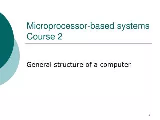
Memory hierarchies Processor Virtual memory Internal memory (operative) Cache SRAM DRAM HD, CD, DVD
Principles in favor of memory hierarchies • Temporal locality – if a location is accessed at a given time it has a high probability of being accessed in the near future • examples: exaction of loops (for, while, etc.), repeated processing of some variables • Spatial locality – if a location is accessed than its neighbors have a high probability of being accessed in the near future • examples: loops, vectors and records processing • 90/10 – 90% of the time the processor executes 10% of the program • The idea: to bring memory zones with higher probability of access in the future, closer to the processor
Cache memory • High speed, low capacity memory • The closest memory to the processor • Organization: lines of cache memories • Keeps copies of zones (lines) from the main (internal) memory • The cache memory is not visible for the programmer • The transfer between the cache and the internal memory is made automatically under the control of the Memory Management Unit (MMU)
Design of cache memory • Design problems: 1. Which is the optimal length of a cache line ? 2. Where should we place a new line ? 3. How do we find a location in the cache memory ? 4. Which line should be replace if the memory is full and a new data is requested ? 5. How are the “write” operations solved ? • Cache memory architectures: • cache memory with direct mapping • associative cache memory • set associative cache memory • cache memory organized on sectors
Cache memory with direct mapping • Principle: the address of the line in the cache memory is determined directly from the location’s physical address – direct mapping • the tag is used to identify lines with the same position in the cache memory • Advantages: • simple to implement • easy to place, find and replace a cache line • Drawbacks: • in some cases, repeated replacement of lines even if the cache memory is not full • inefficient use of the cache memory space
Associative cache memory • Principle: • a line is placed in any free zone of the cache memory • a location is found comparing its descriptor with the descriptors of lines present in the cache memory • hardware comparison – (too) many compare circuits • sequential comparison –too slow • advantages: • efficient use of the cache memory's capacity • Drawback: • limited number of cache lines, so limited cache capacity – because of the comparison operation
Set associative cache memory • Principle: combination of associative and direct mapping design: • lines organized on blocks • block identification through direct mapping • line identification (inside the block) through associative method • Advantages: • combines the advantages of the two techniques: • many lines are allowed, no capacity limitation • efficient use of the whole cache capacity • Drawback: • more complex implementation
Cache memory organized on sectors • Principle: similar with the Set associative cache, but: • the order is changed, the sector (block) is identified through associative method and the line inside the sector with direct mapping • Advantages and drawbacks: similar with the previous method
Writing operation in the cache memory • The problem: writing in the chache memory generates inconsistency between the main mamory and the copy in the cache • Two techniques: • Write back – writes the data in the internal memory only when the line is downloaded (replaced) from the cache memory • Advantage: write operations made at the speed of the cache memory – high efficiency • Drawback: temporary inconsistency between the two memories – it may be critical in case of multi-master (e.g. multi-processor) systems, because it may generate errors • Write through – writes the data in the cache and in the main memory in the same time • Advantage: no inconsistency • Drawback: write operations are made at the speed of the internal memory (much lower speed) • but, write operations are not so frequent (1 write from 10 read-write operations)
The efficiency of the cache memory • ta = tc + (1-Rs)*ti • where: • ta – average access time • ti – access time of the internal memory • tc – access time of the cache memory • Rs – success rate • (1-Rs) – miss rate
Virtual memory • Objectives: • Extension of the internal memory over the external memory • Protection of memory zones from un-authorized accesses • Implementation techniques: • Paging • Segmentation
Segmentation • Divide the memory into blocks (segments) • A location is addressed with: • Segment_address+Offset_address = Physical_address • Attributes attached to a segment control the operations allowed in the segment and describe its content • Advantages: • access of a program or task is limited to the locations contained in segments allocated to it • memory zones may be separated according to their content or destination: cod, date, stivă • a location address inside of a segment require less address bits – it’s only a relative/offset address • consequence: shorter instructions, less memory required • segments may be placed in different memory zones • changing the location of a program does not require the change of relative addresses (e.g. label addresses, variable addresses)
Segmentation for Intel Processors Address computation in Real mode Address computation in Protected mode
Segmentation for Intel Processors • Details about segmentation in Protected mode: • Selector: • contains: • Index – the place of a segment descriptor in a descriptor table • TI – table identification bit: GDT or LDT • RPL – requested privilege level – privilege level required for a task in order to access the segment • Segment descriptor: • controls the access to the segment through: • the address of the segment • length of the segment • access rights (privileges) • flags • Descriptor tables: • General Descriptor Table (GDT) – for common segments • Local Descriptor Tables (LDT) – one for each task; contains descriptors for segments allocated to one task • Descriptor types: • Descriptors for Code or Data segments • System descriptors • Gate descriptors – controlled access ways to the operating system
Protection mechanisms assured through segmentation (Intel processors) • Accessto the memory (only) through descriptors preserved in GDT and LDT • GDT keeps the descriptors for segments accessible for more tasks • LDT keeps the descriptors of segments allocated for just one task => protected segments • Read and write operations are allowed in accordance with the type of the segment (Code of data) and with some flags (contained in the descriptor) • for Code segments: instruction fetch and maybe read data • for Data segments: read and maybe write operations • Privilege levels: • 4 levels, 0 most privileged, 3 least privileged • levels 0,1, and 2 allocated to the operating system, the last to the user programs • a less privileged task cannot access a more privileged segment (e.g. a segment belonging to the operating system)
Paging • Internal and external memory is divided in blocks (pages) of fixed length • The internal memory is virtually extended over the external memory (e.g. hard disc) • Only those pages are brought in the internal memory that have a high probability of being used in the future • justified by the temporal and spatial locality and 90/10 principles • Implementation – similar with the cache memory • Design issues: • Optimal dimension of a page • Placement of a new page in the internal memory • Finding the page in the memory • Selecting the page for download – in case the internal memory is full • Implementation of “write” operations
Paging – Write operation • Problem: inconsistency between the internal memory and the virtual one • it is critical in case of multi-master (multi-processor) systems • Solution: Write back • the write through technique is not feasible because of the very low access time of the virtual (external) memory