IPv4: Internet Protocol
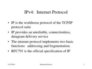
IPv4: Internet Protocol. IP is the workhorse protocol of the TCP/IP protocol suite IP provides an unreliable, connectionless, datagram delivery service The internet protocol implements two basic functions: addressing and fragmentation. RFC791 is the official specification of IP. User

IPv4: Internet Protocol
E N D
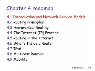
Presentation Transcript
IPv4: Internet Protocol • IP is the workhorse protocol of the TCP/IP protocol suite • IP provides an unreliable, connectionless, datagram delivery service • The internet protocol implements two basic functions: addressing and fragmentation. • RFC791 is the official specification of IP Internet Protocol
User Process User Process User Process User Process The Workhorse application TCP UDP transport ICMP IP IGMP network Hardware Interface link ARP RARP Internet Protocol
IP Header 8 16 31 Version Hdr Len Type of Service Total Length (in bytes) Identification Flags Fragment offset 20 bytes Time to Live Protocol Checksum Source IP Address Destination IP Address options (if any) data Internet Protocol
Network Byte Ordering • Multi-byte numbers can be stored in one of two ways: • 6000010 = 00000000 00000000 11101010 01100000 • Network byte order is big endian Internet Protocol
IP Header Fields Internet Protocol
Type of Service • The IP protocol provides a (rather limited) facility for upper layer protocols to convey hints to the Internet Layer about how the tradeoffs should be made for the particular packet 3-bit precedence 4-bit TOS MBZ Internet Protocol
TOS Field Values • There are 4 defined values for the TOS field • Note these values are defined as integers, not as bits Internet Protocol
Recommended TOS Values Internet Protocol
Fragmentation • The physical layer often imposes an upper limit on the size of the frame that can be transmitted • IP compares the MTU (maximum transmission unit) with the datagram size and performs fragmentation, if necessary • Fragmentation can take place at the original host or at an intermediate router • IP datagrams are not reassembled until they reach their final destination Internet Protocol
Fragmentation and the Header • The following fields are used in fragmentation • identification • contains a unique value for each IP datagram that the sender transmits • flags • fragment offset • the offset of the fragment from the beginning of the original datagram MBZ checking bit Don’t fragment More fragments Internet Protocol
Fragmentation • If fragmentation must occur… • if the “don’t fragment” bit is turned on the packet is discarded • the packet is split into fragments • the header is basically copied except for… • total length is changed to the size of the fragment • the fragmentation offset is set to the the offset of the fragment from the beginning of the original datagram • the “more fragments” bit is turned on in every fragment except for the last one Internet Protocol
Reassembly • The identification field is used to ensure that fragments of different datagrams are not mixed. • The fragment offset field tells the receiver the position of a fragment in the original datagram • The fragment offset and length determine the portion of the original datagram covered by this fragment • The more-fragments flag indicates (by being reset) the last fragment Internet Protocol
Protocol Field • This field indicates the next level protocol used in the data portion of the internet datagram • The values for various protocols are specified in RFC1060 (Assigned Numbers) Internet Protocol
Decimal Keyword Protocol References 0 Reserved [JBP] 1 ICMP Internet Control Message [97,JBP] 2 IGMP Internet Group Management [43,JBP] 3 GGP Gateway-to-Gateway [60,MB] 4 Unassigned [JBP] 5 ST Stream [49,JWF] 6 TCP Transmission Control [106,JBP] 7 UCL UCL [PK] 8 EGP Exterior Gateway Protocol [123,DLM1] 9 IGP any private interior gateway [JBP] 10 BBN-RCC-MON BBN RCC Monitoring [SGC] 11 NVP-II Network Voice Protocol [22,SC3] 12 PUP PUP [8,XEROX] 13 ARGUS ARGUS [RWS4] 14 EMCON EMCON [BN7] 15 XNET Cross Net Debugger [56,JFH2] 16 CHAOS Chaos [NC3] 17 UDP User Datagram [104,JBP] 18 MUX Multiplexing [23,JBP] 19 DCN-MEAS DCN Measurement Subsystems [DLM1] 20 HMP Host Monitoring [59,RH6] 21 PRM Packet Radio Measurement [ZSU] 22 XNS-IDP XEROX NS IDP [133,XEROX] Internet Protocol
Header Checksum • The header checksum is calculated over the IP header only • The checksum is calculated as follows: • set the checksum field to 0 • Add all the 16 bit values in the header together, minus the checksum • Take the one’s complement of the calculated value • the 16-bit one’s complement of this sum is stored in the checksum field Internet Protocol
Header Checksum • When an IP datagram is received, the 16-bit one’s complement sum of the header is calculated • Since the receiver’s calculated checksum contains the checksum stored by the sender, the calculated result should be all ones • If the checksum is wrong, the packet is quietly discarded. No error messages are generated • ICMP, IGMP, UDP, and TCP all use the same checksum Internet Protocol
Addressing • A distinction is made between names, addresses, and routes • A name indicates what we seek • An address indicates where it is • A route indicates how to get there • The internet protocol deals primarily with addresses. It is the task of higher level protocols to make the mapping from names to addresses. Internet Protocol
IP Addresses • Every interface on the internet must have a unique Internet Address (also called an IP address) • IP addresses are 32-bits numbers • The addresses are not flat, they are divided into two components: the host address and the network address • The number of bits assigned to the host portion and network portion of the address varies depending on the class of the address Internet Protocol
IP Address Classes 7 bits 24 bits Class A 0 netid hostid 14 bits 16 bits Class B 1 0 netid hostid 21 bits 8 bits Class C 1 1 0 netid hostid 28 bits Class D 1 1 1 0 multicast group ID 27 bits Class E 1 1 1 1 0 (reserved for future use) Internet Protocol
Dotted Decimal Notation • IP addresses are normally written as four decimal numbers, one for each byte of the address. • 129.21.38.169 • The easiest way to differentiate between the classes is to look at the first number Internet Protocol
Assigning IP Addresses • Since every interface must have a unique IP address, there must be a central authority for assigning numbers • That authority is the Internet Network Information Center, called the InterNIC. • The InterNIC assigns only network ids, the assignment of host ids is up to the system administrator Internet Protocol
Subnet Addressing • The original view of the Internet universe was a two-level hierarchy: • the top level the Internet as a whole • the level below it individual networks, each with its own network number. • In this two-level model, each host sees its network as a single entity Internet Protocol
Subnet Addressing • While the two-level view has proved simple and powerful, a number of organizations have found it inadequate, and have added a third level to the interpretation of Internet addresses. • In this view, a given Internet network is divided into a collection of subnets. • The three-level model is useful in networks belonging to moderately large organizations Internet Protocol
Subnet Addressing • Locally IP addresses consist of three parts: • network ID • subnet ID • host ID • Outside of the subnetted network the addresses are handled normally • Inside the subnet, the network portion of the address is extended for local routing purpose Internet Protocol
Subnet Masks • Once the decision to subnet has been made, the local administrator must decide how many bits to allocate to the subnet ID • A common division is to use the 8-bit boundary in the 16 bits of a host ID in a class B address • A subnet mask is used to divide the local address into network and host portions • Subnetting effectively hides the details of the internal network to external routers Internet Protocol
Special IP Addresses Internet Protocol
IP Options Field • The options field is a variable-length list of optional information for the datagram • The options currently defined are • security and handling restrictions (RFC1108) • record route • timestamp • loose & strict source routing • The options field always ends on a 32-bit boundary Internet Protocol
IP Routing • Routing is one of the most important functions of IP • Datagrams to be routed can either be generated on the local host or on some other host • If a machine is not configured as a router, datagrams received through network interfaces that are not addressed to the machine are dropped Internet Protocol
Host Routing • Conceptually IP routing is easy, especially for a host • Remember the structure of an internet address • If the destination is directly connected to the host, or on a shared network, then the datagram is sent directly • Otherwise the host sends the datagram to a default router, and lets the router do all of the work Internet Protocol
IP routing Algorithm • The basic internet routing algorithm is used by both hosts and routers • The primary difference is that hosts never forward datagrams (except to a default router), whereas routers forward datagrams • The algorithm uses a routing table to make routing decisions Internet Protocol
A Typical Routing Table • Each entry in the routing table contains the following information • Destination IP address. • this can be either a host address or a network address • IP address of the next-hop router, or the IP address of a directly connected network • Flags that tell more about the entry • Which interface the datagram should be passed to for delivery Internet Protocol
IP routing • IP routing performs the following actions • search the routing table for an entry that matches the complete destination address. If found, send the packet as indicated • search the routing table for a matching destination network ID. If found, send the packet as indicated • search the routing table for a default entry. If found send the packet as indicated • If none of the steps work, the datagram is undeliverable Internet Protocol
IP Layer Routing Internet Protocol
IP Routing • The routing done by IP, when it searches the routing table and decides which interface to send a packet out, is a routing mechanism • A routing policy is a set of rules that determines which routes go into the routing table. • IP performs the routing mechanism while a routing daemon normally provides the routing policy. Internet Protocol
Initializing a Routing Table • One common way is to execute the route command explicitly from the initialization files when the system is being bootstrapped. • Some systems allow a default router to be specified in a file such, and this default is added to the routing table on every reboot. • Other ways to initialize a routing table are to run a routing daemon or to use the newer router discovery protocol. Internet Protocol
Routing Errors • What happens if there is no default route, and a match is not found for a given destination? • If the datagram was generated locally, an error is returned to the application that sent the datagram (either “host unreachable” or “network unreachable”) • What do I do if I am a router? • Sender should be notified of the error Internet Protocol