Download
1 / 12
120 likes | 214 Vues
Learn about minimizing vertical emittance by removing cross-plane couplings. Explore skew correction sub-system and emittance measurement.

E N D
Optics for Skew Correction and Emittance Measurement Leo Jenner This talk is going to look familiar if you were at the recent LC-ABD meeting in Manchester…
<x2> <xx’> <xy> <xy’> <xx’> <x’2> <x’y> <x’y’> <xy> <x’y> <y2> <yy’> <xy’> <x’y’> <yy’> <y’2> = s 4D symmetric beam matrix To minimise the vertical emittance, especially for a flat beam, it is desirable to remove any cross-plane (x-y) correlations/couplings Coupling terms
Sources of Skew Linac is main source of skew in ILC Skew correction section comes immediately afterwards and is the first sub-system of BDS
Ideal Skew Correction + Emittance Measurement Layout 4 orthogonal skew quadrupoles correct xy, x’y’, x’y, xy’ 4 wire scanners / laser wires for emittance measurement
4D measurement simulation – 6 wire scanners required Measured Emittance Input Emittance Perturbed Projected Emittance Unperturbed Projected Emittance High Rejection Factor with realistic measurement errors
2D Measurement simulation with 4 wires scanners Calculated projected emittance Only 4 scanners – shorter, cheaper Scan in x and y separately Coupling is inferred from difference between measured and expected emittance – it seems this is good enough! Unperturbed projected emittance
Correction procedure • Perturb beam with skew quads • Measure beam parameters with scanners • Infer coupling • Calculate skew correction • Apply to skew quadrupoles • (Iterate)
Skew Quad Scanning Scan quad strength around nominal value to find minimum Fit parabola Extract parameters
Coupling Correction in Action Projected/Actual emittance Skew Quad Scan Number
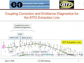
Application 2: ILC BDS Skew Section
Summary and Future Plans • Use ‘real’ ILC errors • Investigate alternative 4D methods • Investigate 2D/4D and/or BPM method • Incorporate simulation of Laserwire • Tweaking of ATF2/ILC optics