8254 Timer & Counter Programming Guide
Learn how to program the 8254 timer and counter IC, control registers, modes of operation, and programming commands. Understand the pin diagram, counter selection, and usage of the 8253/8254 timers and counters for frequency division and wave generation.

8254 Timer & Counter Programming Guide
E N D
Presentation Transcript
8254 Timer and Counter (8254 IC)
Programmable Timer 8254 Timer and Counter (8254 IC)
Pin Diagram Timer and Counter (8254 IC)
Counter Selection A0 Select 0 0 0 Counter 0 0 0 1 Counter 1 0 1 0 Counter 2 0 1 1 Control Reg. Timer and Counter (8254 IC)
8254 Programming Read Back Command Timer and Counter (8254 IC)
Mode of Operation Timer and Counter (8254 IC)
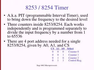
8253 / 8254 Timer • Each of the three counter has 3 pins associated • CLK: input clock frequency 8253: 0 ~ 2 MHz, 8254: 0 ~ 8 MHz • OUT: can be square wave, or one shot • GATE: Enable (high) or disable (low) the counter • Data Pins: (D0 ~ D7) • Allow the CPU to access various registers inside the 8253/54 for both read and write operations. RD and WR are connected to IOR and IOW of control bus. Timer and Counter (8254 IC)
8253 / 8254 Timer • Each of the three counters must be programmed separately • Control byte must be first written into the control register. The 8253/54 must be initialized before use • The programmer can not only write the value of the divisor into the 8253/54, but read the content of the counter at any given time as well • All counters are down counters. Timer and Counter (8254 IC)
8253 / 8254 Timer • To program a given counter to divide the CLK input frequency, one must send the divisor to that specific counter’s register. • Although all three counters share the same control register, the divisor registers are separate for each counter • Example: given the port addresses for 8254: Counter 0: 80H Counter 1: 81H Counter 2: 82H Control Reg: 83H Timer and Counter (8254 IC)
8254 Programming • Each counter may be programmed with a count of 1 to FFFFH. • Each counter has a program control word used to select the way the counter operates. • If two bytes are programmed, then the first byte (LSB) stops the count, and the second byte (MSB) starts the counter with the new count. Timer and Counter (8254 IC)
1 OUTPUT 1 NULL COUNT COUNT RW1 STATUS RW0 M2 CNT2 CNT1 M1 M0 CNT0 0 BCD 8254 Read Back Command • 8254 Read Back Command • 8254 status word format Timer and Counter (8254 IC)
8254 Modes • Mode 0: An events counter enabled with G. • The output becomes a logic 0 when the control word is written and remains there until N plus the number of programmed counts. • Gate signal has to be high to initialize the count. Timer and Counter (8254 IC)
8254 Modes Mode 1: One-shot mode. • The G input triggers the counter to output a 0 pulse for `count' clocks. • Counter reloaded if G is pulsed again. Timer and Counter (8254 IC)
8254 Modes • Mode 2:Rate Generator: Counter generates a series of pulses 1 clock pulse wide. • The seperation between pulses is determined by the count. • The cycle is repeated until reprogrammed or G pin set to 0. Reloaded Timer and Counter (8254 IC)
8254 Modes • Mode 3: Square Wave Generator: Generates a continuous square-wave with G set to 1. • If count is even, 50% duty cycle otherwise OUT is high 1 cycle longer. Timer and Counter (8254 IC)
8254 Modes • Mode 4: Software triggered one-shot (G must be 1). In this mode OUT is initially high; it goes low for one clock period at the end of the count. The count must be RELOADED -(UNLIKE MODE 2) for subsequent outputs. Timer and Counter (8254 IC)
Mode 5 • This mode is similar to MODE 4 except that it is triggered by the rising pulse at the gate. Initially, the OUT is low and when the GATE pulse is triggered from low to high , the count begins. At the end of the count the OUT goes low for one clock period. Timer and Counter (8254 IC)