Using the 8254 Timer-Counter
Learn how the 8254 timer-counter works in the PC system, used for generating interrupts, memory refresh, and speaker beeps. Explore the algorithm for displaying time-of-day and controlling timer channels. Discover how to convert ticks to seconds and program the PIT for specific functions.


Using the 8254 Timer-Counter
E N D
Presentation Transcript
Using the 8254 Timer-Counter Understanding the role of the system’s 8254 programmable Interval-Timer/Counter
The 8254 PIT • The 8254 Programmable Interval-timer is used by the PC system for (1) generating timer-tick interrupts (rate is 18.2 per sec), (2) performing dynamic memory-refresh (reads ram once every 15 microseconds), and (3) generates ‘beeps’ of PC speaker • When the speaker-function isn’t needed, the 8254 is available for other purposes
Displaying ‘Time-Of-Day’ • Algorithm steps: • Get the count of timer-interrupts so far today • Convert these ‘timer-ticks’ into seconds • Breakdown the total number of seconds today into Hours, Minutes, Seconds, and AM/PM • Convert numerical values into digit-strings • Output these results to the video terminal
Where’s the ‘tick’ counter? main memory Number of timer-tick interrupts so far today (longword at 0x0046C) 0x00500 ROM-BIOS DATA AREA 0040:006C tick_count 0x00400 Interrupt Vector Table (for real-mode) 0x00000
Getting the ‘tick’ count • The ROM-BIOS interrupt-handler for the timer interrupt stores the tick-count as a 32-bit integer located at address 0x046C (it’s in the ROM-BIOS DATA AREA) • In real-mode, we can get it like this: xor %ax, %ax # address segment zero mov %ax, %fs # using FS register mov %fs:0x046C, %eax # copy tick-count to EAX mov %eax, total_ticks # save in a local variable segment-override prefix (segment used would be %ds)
Converting ‘ticks’ to seconds total_ticks_today total_seconds_today = number of ticks-per-second The number of ‘ticks-per-second’ is based upon the way the PC’s timing hardware has been programmed
Input/Output frequencies • The input-pulses to each Timer-channel is a long established PC standard, based on the design of the chrystal oscillator chip: 1,193,182 pulses-per-second (Hertz) • The frequency of the output-pulses from any Timer-channel is determined by how that channel’s Latch was programmed
Three timer/counter ‘channels’ 8284 PCLK 1193182 Hz Channel 0 CLK0 OUT0 Interrupt IRQ0 GATE0 Port 0x61, bit #4 CLK1 Channel 1 OUT1 DRAM refresh GATE1 Port 0x61, bit #5 CLK2 Channel 2 OUT2 GATE2 speaker AND Port 0x61, bit #0 8254 PIT +5 V Port 0x61, bit #1
Controlling timer-channel 2 I/O port 0x61 (aka ‘Port_B’) 7 6 5 4 3 2 1 0 r/o r/o r/o r/o r/w r/w r/w r/w OUT2 status OUT1 status SPKR control GATE2 control RAM parity checking enabled I/O channel checking enabled RAM parity error I/O channel error
Counter decrements when pulsed COUNT REGISTER CLK MSB LSB OUT MSB LSB LATCH REGISTER GATE STATUS TIMER/COUNTER CHANNEL
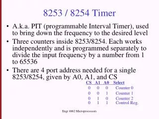
8254 Command-Port 7 6 5 4 3 2 1 0 CHANNEL COMMAND OUTPUT MODE binary / BCD Output Mode 000 = one-shot level 001 = retriggerable 010 = rate-generator 011 = square-wave 100 = software strobe 101 = hardware strobe Counting Mode 0 = binary 1 = BCD Channel-ID 00 = chn 0 01 = chn 1 10 = chn 2 Command-ID 00 = Latch 01 = LSB r/w 10 = MSB r/w 11 = LSB-MSB r/w Commands are sent to the 8254 via io/port 0x43
Programming a PIT channel • Step 1: send command to PIT (port 0x43) • Step 2: read or write the channel’s Latch • via port 0x40 for channel 0 • via port 0x41 for channel 1 • via port 0x42 for channel 2
A ten-millisecond delay • In future lessons we will want to create a time-delay of ten-milliseconds (allowing some hardware to finish its initialization) • We can do it using the Timer Channel 2 • We program its ‘Latch Register’ with the Timer Input-Pulse Frequency, multiplied by 1/100 (i.e., 1193182 / 100 = 11932) • We specify the ‘one-shot’ counting mode
Code for the 10ms delay # enable Timer Channel 2 in $0x61, %al and $0x0C, %al or $0x01, %al out %al, $0x61 # program Channel 2 for “one-shot” countdown mov $0xB0, %al out %al, $0x43 # write Channel 2 Latch-Register (LSB/MSB) mov $11932, %ax out %al, $0x42 mov %ah, %al out %al, $0x42 # delay until OUT2 signal is activated (bit 5) poll: in $0x61, %al test $0x20, %al jz poll # disable Timer Channel 2 in $0x61, %al and $0x0C, %al out %al, $0x61
Standard BIOS programming • For Channel 0 (the ‘timer-tick’ interrupt) the Latch is programmed during system startup with a value of zero • But the Timer interprets zero as 65,536 • So the frequency of the output-pulses from Timer-channel 0 is equal to this quotient: output-frequency = input-frequency / frequency-divisor = 1193182 / 65536 (approximately 18.2)
Consequently… • To compute ‘total_seconds’ from ‘total_ticks’: total_seconds = total_ticks / ticks_per_second = total_ticks / (1193182 / 65536) = ( total_ticks * 65536 ) / 1193183 • We can use the x86 CPU’s integer-arithmetic instructions MUL (multiply) and DIV (divide)
How ‘MUL’ works Before executing the MUL instruction… EAX multiplicand (32-bits) reg (or mem) multiplier (32-bits) 32-bit operands mull reg_or_mem Here’s the instruction… After executing the MUL instruction… product (64-bits) EDX EAX 64-bit product
How ‘DIV’ works Before executing the DIV instruction… dividend (64-bits) EDX EAX 64-bit dividend reg (or mem) divisor (32-bits) 32-bit operand divl reg_or_mem Here’s the instruction… After executing the DIV instruction… two results (32-bits) EDX EAX 32-bit remainder 32-bit quotient
Implementing the conversion • So use MUL and DIV to convert ‘ticks’ into ‘seconds’, like this: # total_seconds = ( total_ticks * FREQ_DIVISOR ) / PULSES_PER_SEC mov total_ticks, %eax mov $FREQ_DIVISOR, %ecx mul %ecx mov $PULSES_PER_SEC, %ecx div %ecx mov %eax, total_seconds # Now integer-quotient is in EAX, and integer-remainder is in EDX
‘Time-Of-Day’ Format HH:MM:SS am/pm hours seconds morning or afternoon minutes So we need to compute four numerical values from the ‘total_seconds’ integer
Our four time-parameters We use these arithmetical ideas: • total_minutes = ( total_seconds / 60 ); ss = ( total_seconds % 60 ); • total_hours = (total_minutes / 60 ); mm = ( total_minutes % 60 ); • total_halfdays = (total_hours / 12 ); hh = (total_hours % 12 ); • Total_days = ( total_halfdays / 2 ); xm = total_halfdays % 2;
A subtle refinement • Our ‘total_seconds’ value was gotten with an integer-division operation, so there’s likely to be some ‘round-off’ error • How can we be sure we use the ‘closest’ integer to the actual quotient? • We should remember the ‘rounding’ rule! • When ‘remainder’ is equal or greater than 1/2 of ‘divisor’, ‘quotient’ gets incremented
How to implement rounding? • There is more than one way to do it – i.e., the “amateur’s” way or the “expert’s” way • Knowledge of the CPU’s architecture and instruction-set can assist • The ‘obvious’ method: • if ( 2 * remainder >= divisor ) ++quotient; • But this uses a multiply and a conditional jump-instruction (inefficient!)
Avoiding inefficiency… • Replace the ‘multiply’ with an ‘addition’ • Use ‘subtract’ and ‘add-with-carry’ instead of using ‘compare’ and ‘conditionally-jump’ # Recall: quotient was in EAX, remainder was in EDX, divisor was in ECX add %edx, %edx # doubles the remainder sub %ecx, %edx # computes: 2*quotient – divisor # now carry-flag is clear in case 2*quotient >= divisor cmc # complement the carry-flag bit # now carry-flag is set in case 2*quotient >= divisor adc $0, %eax # add the carry-flag to the quotient # So this achieves the same effect as the ‘rounding rule’, but wit no jump!
In-class exercise • Can you enhance our ‘timeoday.s’ demo to make it more dramatic (and later useful) by creating a loop within its ‘main’ routine, so that it continues to read and display the time (until the user presses a key)? • HINTS: Use an INT-0x16 keyboard service to ‘peek’ into the keyboard-queue, and omit the ‘\n’ (newline) control-code from the ‘report’ message-string