Download
1 / 27
270 likes | 311 Vues
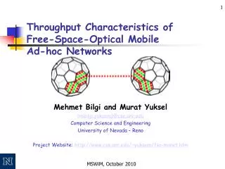
Explore the potential of Free-Space Optical (FSO) technology in mobile ad-hoc networks, comparing it with RF, discussing propagation models, literature insights, and challenges such as LOS requirements. Discover the advantages of FSO like cost-effectiveness and high speeds along with disadvantages including LOS issues. Dive into FSO literature on high-speed applications and innovative deployment methods.

E N D
Capacity Scaling in Free-Space-Optical Mobile Ad-Hoc Networks Mehmet Bilgi University of Nevada, Reno
Agenda • RF and FSO Basics • FSO Propagation Model • FSO in Literature • Mobility Model and Alignment • Simulation Results • Conclusions • Future Work
RF and FSO Illustration Different natures of two technologies: omni-directional and directional Receiver Transmitter Receiver Directional FSO antenna Transmitter Omni-directional RF antenna
RF Saturation • A well-known fact: RF suffers from frequency saturation and RF-MANETs do not scale well • √n as n is increased [1] • Linear scalability can be achieved with hierarchical cooperative MIMO [2] imposing constraints on topology and mobility pattern • Omni-directional nature of the frequency propagation causes: • Channel is a broadcast medium, overhearing • Security problems • Increased power consumption to reach a given range • End-to-end per-node throughput vanishes: approaches to zero as more nodes are added 1 Gupta, P. Kumar, P.R. , The capacity of wireless networks, IEEE Transactions on Information Theory, ‘00 2 Ozgur et al., Hierarchical Cooperation Achieves Optimal Capacity Scaling in Ad Hoc Networks, IEEE Transactions on Information Theory, ‘06
Fiber Optical Solutions • As of 2003; • Only ~5% of buildings have fiber connections • ~75% of these buildings are within 1 mile range of fiber • Laying fiber to every house and business is costly and takes a long time • Considered as sunk cost: no way to recover • Purchase land to lay fiber • Digging ground • Maintenance of fiber cable is hard • Modulation hardware is sensitive and expensive • ISPs are uneager to deploy aggressively because of initial costs • They are deploying gradually • Attempts existed in near past: • California, Denver, Florida (before 2000) 1 Source: 02-146 ExParte FCC WTB Filing by Cisco Systems, May 16, 2003
FSO Advantages • Materials: cheap LEDs or VCSELs with Photo-Detectors, commercially available, <$1 for a transceiver pair • Small (~1mm2), low weight (<1gm) • Amenable to dense integration (1000+ transceivers possible in 1 sq ft) • Reliable (10 years lifetime) • Consume low power (100 microwatts for 10-100 Mbp) • Can be modulated at high speeds (1 GHz for LEDs/VCSELs and higher for lasers) • Offer highly directional beams for spatial reuse/security • Propagation medium is free-space instead of fiber, no dedicated medium • No license costs for bandwidth, operate at near-infrared wavelengths
FSO Disadvantages • FSO requires clear line-of-sight (LOS) • Maintaining LOS is hard even with slight mobility • Node often looses its connectivity: intermittent connectivity • Loss of connectivity is different than RF’s channel fading • Investigated the effects of intermittent connectivity on higher layers: • Especially TCP
FSO Propagation Model • Atmospheric attenuation, geometric spread and obstacles contribute to BER • Atmospheric attenuation: • Absorption and scattering of the laser light photons by the different aerosols and gaseous molecules in the atmosphere • Mainly driven by fog, size of the water vapor particles are close to near-infrared wavelength • Bragg’s Law [1]: • σ is the attenuation coefficient, defined by Mie scattering: • V is the atmospheric visibility, q is the size distribution of the scattering particles whose value is dependent on the visibility 1 H. Willebrand and B. S. Ghuman. Free Space Optics. Sams Pubs, 2001. 1st Edition.
Error in the approximate model Uncovered Area Coverage Area FSO Transmitter (e.g. LED) Geometrical Spread of the Beam Rmax (receiver radius) R FSO Receiver (e.g. PD) Maximum range (Lambertian model) Maximum range (our approximate model: “triangle + half-circle”) FSO Propagation Model • Geometric spread is a function of • transmitter radius γ, • the radius of the receiver ς, • divergence angle of the transmitter θ, • the distance between the transmitting node and receiving node R [1]: 1 H. Willebrand and B. S. Ghuman. Free Space Optics. Sams Pubs, 2001. 1st Edition.
Traditional roof-top FSO deployment FSO Literature – High Speed • Terrestrial last-mile applications • Roof-top deployments • Metropolitan / downtown areas • Point-to-point high speed links • Use high-powered laser light sources • Use additional beams to handle swaying of buildings • Gimbals for tracking the beam • Limited spatial reuse • Some indoor applications with diffuse optics (more on this later)
Interconnect with misalignment detector [1] FSO Literature – High Speed • Free-Space-Optical Interconnects • Inside the large computers to eliminate latency • Short distances(1-10s cm) • Remedy vibrations in the environment • Use backup beams, misalignment detectors • Expensive, highly-sensitive tracking instruments • Hybrid FSO/RF applications • Consider FSO as a back-bone technology • No one expects pure-FSO MANETs • Single optical beam • No effort to increase the coverage of FSO via spatial reuse • Deep space communications 1 M. Naruse et al., Real-Time Active Alignment Demonstration for Free-Space Optical Interconnections, IEEE Photonics Tech. Letters, Nov. 2001
FSO Literature • Mobile FSO Communications • Indoor, single room using diffuse optics • Suitable for small distances • Outdoor (roof-top and space) studies focus on swaying and vibration • Scanning, tracking via beam steering using gimbals, mechanical auto-tracking • Instruments are slow and expensive • We propose electronical steering methods • Effects of directional communication on higher layers • Choudhury et al. worked on RF directionality, directional MAC • Traditional flooding based routing algorithms are effected badly • Directionality must be used for localization also (future work)
Multi-element optical antenna design: Honeycombed arrays of directional transceivers Mobility Model • Design an antenna with FSO transceivers to • Exploit directionality and spatial reuse • Target mobility • Multi-element antenna using commerciallyavailable components • Disconnections will still occur • But with a reduced amount • Recoverable with special techniques (auto-alignment circuit) • Our work: FSO in MANET context with mobility
1 1 2 2 8 8 3 3 7 7 6 6 4 4 5 5 Mobility Model in NS-2 • No network simulator has FSO simulation capabilities • Each transceiver keeps track of its alignments • A table based implementation • Alignment timers • Example scenario: • 2 nodes with 8 interfaces each • Node-B has relative mobility w.r.t. Node-A • Observe the changes in alignment tables of 2 different transceivers in two nodes Node-B in Pos-1 Alignment tables in interface 5 of node B and interface 1 of node A Alignment tables in interface 4 of node B and interface 8 of node A Node-B in Pos-2 Alignment tables in interface 3 of node B and interface 7 of node A Node-B in Pos-3 Node-A
Mobility Experiment • Train looses and re-gains its alignment in a short amount of time: intermittent connectivity • Measured light intensity shows the connection profile • Complete disruption of the underlying physical link: different than RF fading • Auto-alignment circuitry: • Monitors the light intensity in all interfaces • Handles auto hand-off among different transceivers • Initiates the search phase • Search Phase: • When misaligned, an interfaces sends out a search signal (pre-determined bit sequence), freq of search signal • Waits for reception • When senses a search signal, responds it • Interfaces restore the data transmission phase • We want to observe TCP behaviour over FSO-MANETs Misaligned Aligned Received Light Intensity from the moving train Aligned Misaligned Detector Threshold Denser packing will allow fewer interruptions (and smaller buffering), but more handoffs.
210 meters 30 meters 210 meters 30 meters Simulations • 49 nodes in a 7 x 7 grid • Every node establishes an FTPsession to every other node: 49x48 flows • 4 interfaces per node, each with its own MAC • 3000 sec simulation time • Divergence angle 200 mrad • Per-flow throughputs are depicted • Random waypoint algorithm, conservative mobility • IEEE 802.11 MAC limitation (20 Mbps)
RF and FSO comparison in stationary case, no mobility Stationary RF and FSO Comparison
RF and FSO comparison with different number of interfaces Stationary RF and FSO Comparison
Mobility Effect in FSO. TCP is adversely effected. Mobile FSO: TCP is adversely affected
RF/FSO comparison w.r.t. Speed Mobile RF and FSO Comparison
Node Density Effect • Fixed power: • 49 nodes • Increase the separation b/w nodes and the area • Keep the source transmit power same • Adjusted power: • 49 nodes • Increase the separation b/w nodes and the area • Adjust the source transmit power so that they can reach increased distance
Both performs poorly in a larger area when power is not adjusted accordingly Node Density with Fixed Power
RF performs better when power is adjusted, Uncovered regions causes FSO’s loss RF’s power consumption is way bigger than FSO’s Node Density with Adjusted Power
Mobile UDP Results UDP and TCP mobile throughput comparison
Conclusions • FSO MANETs are possible and provides significant benefit via spatial reuse • Mobility affects TCP performance severely • RF and FSO are complementary to each other; coverage + throughput
Future Work • Introduce buffers at LL and/or Network Layer • Group concept • Directional MAC • Effect of search signal sending frequency